


AD5933 Impedance Converter: 7 Steps Before Trusting a Sweep

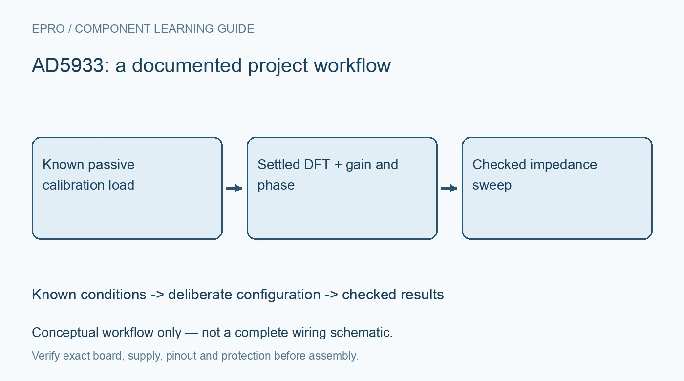
AD5933 Impedance Converter: 7 Steps Before Trusting a Sweep
Plan AD5933 impedance measurements with known calibration parts, correct DFT interpretation and frequency-aware gain and phase corrections. This is a documentation-based planning guide, not a report of independent hands-on testing.
1. Start with passive components only
AD5933 combines a frequency generator, ADC and discrete Fourier transform processing for impedance-measurement systems. Analog Devices describes real and imaginary output codes at each sweep frequency. Begin with known passive resistors in a controlled bench setup, not a human body, energized circuit or an unknown charged component. Discharge capacitors appropriately before connection. This documentation-based guide is not a medical impedance instrument design or a validated method for testing people. Manufacturer documentation.
2. Inspect the complete analog front end
The usable impedance range depends on excitation settings, feedback resistance, gain, biasing and any external analog circuitry. Check the actual carrier schematic instead of treating the chip feature list as a universal measurement range. Verify supply and I2C levels, and confirm the clock source used by the frequency calculation. Output impedance and input-stage limits can affect the result. A board responding on the bus has not yet demonstrated that its analog path is suitable. Manufacturer documentation.
3. Configure a small deliberate sweep
Choose start frequency, increment, number of points and settling cycles using the documented register relationships. Account for the reference clock rather than assuming a library default matches the board. Begin with a narrow sweep and a stable known load. Allow the system to initialize and the excitation to settle before requesting data. Resonant or high-Q networks may need additional settling; an arbitrary short delay is not a universal validation strategy. Manufacturer documentation.
4. Interpret DFT codes correctly
Read a complete valid real-imaginary pair after the status indication reports completed data. Decode signed values and calculate their magnitude without overflowing the arithmetic type. These codes are the processed response of the measurement system, not directly resistance in ohms and reactance in ohms. Preserve raw values with the frequency point. A pair of nonzero registers can still represent stale data, saturation or an unsuitable analog gain setting. Manufacturer documentation.
Newest in the store


5. Calibrate gain with a known impedance
Use a suitable characterized calibration component and the manufacturer procedure to derive the gain factor. Apply the documented relationship between DFT magnitude, admittance and impedance. Keep excitation, gain, feedback network and clock conditions consistent with that calibration. Frequency response can make one calibration factor inadequate across a wide sweep. Use the documented frequency-aware approach and verify it with additional known components instead of assuming a midpoint match guarantees every point. Manufacturer documentation.
6. Correct system phase separately
Calculate phase with a quadrant-aware method consistent with the documented convention. Establish the system phase response using a suitable resistor, then apply the correction at the relevant frequency points. Do not equate the raw DFT angle with the unknown component phase without accounting for the transmit and receive path. Check signs and phase wrapping using a known passive network, keeping component tolerance and parasitic capacitance in mind. Manufacturer documentation.
7. Make the AD5933 sweep reproducible
Export frequency, raw pair, validity, gain calibration, phase correction, component identity and analog settings with each sweep. Repeat a calibration check after changing gain, excitation or the fixture. Avoid claiming laboratory accuracy from one successful resistor test. The linked AD9833 guide introduces frequency-generation concepts but does not provide an impedance front end. A trustworthy AD5933 result follows a documented calibration chain and remains bounded by the analog design, fixture and reference components. Manufacturer documentation.
Related reading: AD9833 DDS: 7 Clock and Output-Load Checks.
Catalog note: The exact-part search did not return a matching Epro listing during preparation. Check the current catalog; this guide makes no price, availability or included-accessory claim.