


BQ24074 Charger: 7 Design Checks for a One-Cell Power Path

BQ24074 Charger: 7 Design Checks for a One-Cell Power Path
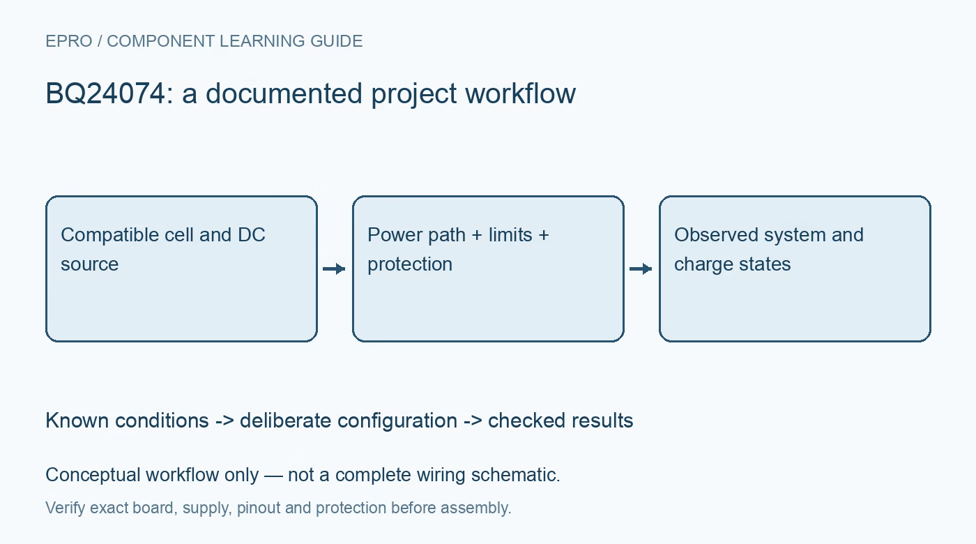
Evaluate BQ24074 one-cell charging with separate system and battery paths, source-current limits, thermal constraints and intact temperature protection. This is a documentation-based planning guide, not a report of independent hands-on testing.
1. Establish the compatible battery system
BQ24074 is a member of the BQ2407x family of standalone single-cell linear chargers with power-path management. Texas Instruments documents variant-specific behavior, so identify the exact device before copying settings. Confirm battery chemistry, permitted charge voltage, current and temperature from the pack manufacturer. A one-cell charger is not suitable for a series pack or an arbitrary lithium chemistry. This is a design-review guide, not a substitute for a qualified battery-product safety assessment. Manufacturer documentation.
2. Keep input, system and battery paths distinct
Understand the IN, OUT and BAT functions from the actual carrier schematic. The power path supplies the system while managing battery charging, rather than treating a permanently attached system load as part of a simple two-terminal charging experiment. Connect a load only through the intended system path. Do not infer wiring from a different family variant or reverse a battery connector. Use a known suitable module and protected compatible pack for a bounded evaluation. Manufacturer documentation.
3. Separate source limit from charge current
The input source has a current budget, while the battery has its own permitted charge current. Configure both according to the exact device and carrier components. System demand and dynamic power-path management can reduce the current available for charging. A nominal charger setting does not prove that the battery receives that current under load. Confirm the source capability and cable losses without treating every USB connector as permission to draw an arbitrary current. Manufacturer documentation.
4. Budget linear-charger dissipation
A linear charger can dissipate substantial heat when voltage drop and charging current are both significant. Evaluate the documented power loss and PCB thermal design instead of assuming the headline current is available continuously. Monitor representative operation using an appropriate safe test arrangement. Thermal regulation reducing charge current is not evidence of a defective battery. Sustained excessive temperature requires redesign or a lower operating demand, not a larger current-setting resistor chosen by trial and error. Manufacturer documentation.
Newest in the store


5. Preserve battery temperature protection
Implement the documented temperature-sense arrangement with a compatible pack or sensing network and retain the required protection behavior. Do not bypass the temperature input merely to clear a fault indication. Keep battery protection, charger control and system safety responsibilities distinct: the charger IC is not a complete protection system for every pack fault. Do not charge damaged, swollen, unidentified or unsuitable cells, and stop an evaluation if abnormal heating or physical damage appears. Manufacturer documentation.
6. Interpret termination and status in context
Review precharge, constant-current, constant-voltage, termination and recharge behavior for the exact configuration. Status pins require correct interpretation and pull-ups; they are not a precision state-of-charge gauge. Confirm how system loading affects the power path and available charge current. Never infer a fully charged battery solely from an arbitrary open-circuit voltage sample or from a status signal wired for another variant. Record input availability and load conditions beside every observed state. Manufacturer documentation.
7. Define the BQ24074 validation boundary
Retain pack specifications, source capability, current-setting components, temperature protection and thermal conditions with the hardware revision. Validate input application and removal only in a suitably protected supervised setup, without creating deliberate battery abuse or fault currents. The linked INA228 guide discusses bounded power logging, not a drop-in charger test circuit. A responsible BQ24074 design combines correct power-path topology with compatible battery limits and independent safeguards; no component guide certifies the finished product as safe. Manufacturer documentation.
Related reading: INA228 Power Monitor: 7 Steps from Shunt Choice to Energy Logs.
Catalog note: The exact-part search did not return a matching Epro listing during preparation. Check the current catalog; this guide makes no price, availability or included-accessory claim.