


ADS1219 ADC: 7 Checks for a Coherent 24-Bit Sensor Record

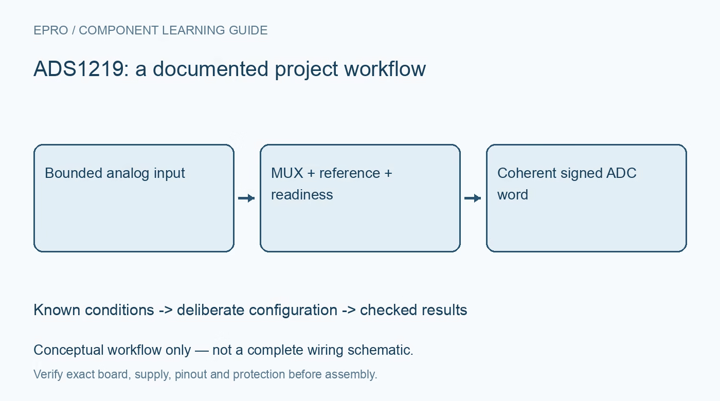
ADS1219 ADC: 7 Checks for a Coherent 24-Bit Sensor Record
Plan ADS1219 acquisition with deliberate input selection, gain, reference, data-ready handling and correct signed 24-bit decoding over I2C. This is a documentation-based planning guide, not a report of independent hands-on testing.
1. Describe the ADS1219 architecture accurately
ADS1219 is a 24-bit delta-sigma converter with a selectable analog input arrangement and I2C interface. Its input multiplexer does not create four simultaneous converters. Decide which differential or single-ended measurement the application requires, and record the selected route. The available gain choices and conversion timing belong in the same configuration description. A marketing phrase such as four-channel ADC is not enough information to reproduce how the host obtained an individual sensor observation. Manufacturer documentation.
2. Establish electrical limits before scaling
Check analog supply, digital supply, input-pin limits and the common reference arrangement for the exact board. A small differential voltage does not guarantee that the absolute voltage at each input pin is acceptable. Review the source circuit and any required protection before connecting it. Keep introductory evaluation in a suitably protected low-voltage setup. Neither high numerical resolution nor a differential input makes the converter an isolated instrument suitable for direct hazardous-voltage measurements. Manufacturer documentation.
3. Select gain and reference as a pair
Choose the documented gain and reference configuration from the expected signal range and its credible variation. Include reference uncertainty and the sensor excitation arrangement in the measurement model. Do not copy an ADS-family conversion constant without confirming the device and actual configuration. Predict clipping boundaries before observing a load. If the reference or gain changes, associate the new configuration with the next accepted sample instead of applying the new scale to an unexplained old result. Manufacturer documentation.
4. Respect the command-based I2C protocol
Use the documented commands for configuration, conversion control and data reading. Verify address pin settings and the transaction sequence used by the host library. A familiar two-wire bus does not imply that arbitrary register helpers provide the intended operation. Confirm the configuration after initialization where the protocol permits. Preserve communication failures separately from conversion values so an unsuccessful read cannot quietly become zero volts or repeat the previous valid sample without a stale indication. Manufacturer documentation.
Newest in the store


5. Use readiness and documented settling behavior
Choose continuous or single-shot acquisition deliberately and use the documented ready indication or status behavior. Review conversion timing when changing the selected input or configuration. The digital filter offers documented settling properties, but those properties do not eliminate settling in an external sensor, filter or switched source. A quick bus read is not proof of a new settled analog observation. Keep sample acceptance tied to the full acquisition sequence rather than a convenient host polling rate. Manufacturer documentation.
6. Decode all 24 bits with the correct sign
The conversion word uses binary two’s complement representation. Assemble the bytes in their documented order and sign-extend the 24-bit value correctly before applying gain and reference scaling. Check negative, zero and positive numerical examples explicitly. Discarding a byte or interpreting the sign as magnitude can still generate convincing small values. Retain the raw word, decoded count and configuration identity together during evaluation so arithmetic faults can be distinguished from analog circuit limitations. Manufacturer documentation.
7. Evaluate useful information rather than bit count
A 24-bit output word does not establish 24 noise-free bits or finished-system accuracy. Evaluate the actual source, reference, wiring, timing and noise under controlled conditions with suitable comparison equipment. Record the input selection and sample time beside each result. The related ADS1120 guide addresses a different converter resolution and interface arrangement, not an interchangeable driver. A useful ADS1219 acceptance record explains which analog quantity was measured and why the reported sample is considered valid. Manufacturer documentation.
Related reading: ADS1120 ADC: 7 Checks for a Valid 16-Bit Conversion.
Catalog note: The exact-part search did not return a matching Epro listing during preparation. Check the current catalog; this guide makes no price, availability or included-accessory claim.