


ADS1120 ADC: 7 Checks for a Valid 16-Bit Conversion

ADS1120 ADC: 7 Checks for a Valid 16-Bit Conversion
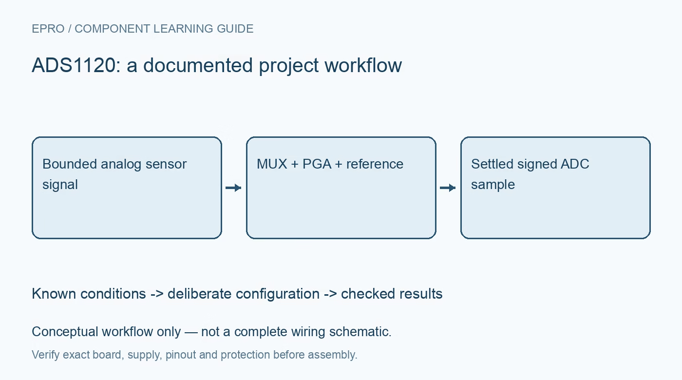
Plan ADS1120 measurements with correct 16-bit decoding, input multiplexing, PGA headroom, reference selection and fresh-conversion timing. This is a documentation-based planning guide, not a report of independent hands-on testing.
1. Keep the ADS1120 resolution distinct
ADS1120 is a 16-bit delta-sigma converter. Do not import the output-word assumptions of the similarly named 24-bit ADS1220. Identify the actual component, carrier and register configuration before selecting a library. The available analog input pins feed a multiplexer rather than four simultaneous independent converters. Define which differential or single-ended measurement is needed and document that input selection. A generic label such as four-channel ADC does not describe the complete acquisition sequence. Manufacturer documentation.
2. Establish a bounded analog input circuit
Review the supply, input limits, protection and common reference arrangement for the exact application. A small differential signal does not imply that both input pins are within their allowed common-mode range. Assess the voltage at each terminal as well as their difference. Keep introductory evaluation within a protected low-voltage circuit and respect source limitations. This converter is not an isolated instrument, and no register configuration makes direct connection to hazardous voltages appropriate. Manufacturer documentation.
3. Choose gain with common-mode headroom
The programmable gain amplifier can help match a small signal to the conversion range, but gain selection also constrains allowable input conditions. Review PGA headroom and the documented bypass options rather than treating the largest gain as automatically best. Predict the input range under normal sensor tolerances and credible operating variation. Record the chosen gain with every measurement configuration. Saturation or an invalid common-mode condition cannot be repaired by applying a different scale factor after acquisition. Manufacturer documentation.
4. Define the reference strategy explicitly
Choose the internal or appropriate external reference arrangement according to the intended sensor and measurement topology. A ratiometric design can reduce sensitivity to certain shared excitation changes, but only when the signal and reference actually have the intended relationship. Check reference limits and wiring from the documentation. If excitation current sources are used, analyze their permitted operating conditions and routing separately. Do not assume an excitation feature turns an arbitrary sensor connection into a complete validated measurement circuit. Manufacturer documentation.
Newest in the store


5. Make channel changes part of the timing model
Select data rate and operating mode with the sensor’s response and interference environment in mind. After changing inputs or configuration, follow the documented conversion and settling requirements before accepting data. A fast SPI transaction is not evidence of a fresh settled conversion. Define whether the host uses single-shot or continuous operation, how readiness is detected and how configuration changes are associated with the next accepted sample in the record. Manufacturer documentation.
6. Decode signed data and preserve status
Reconstruct the 16-bit conversion word using the documented byte order and signed representation. Apply the selected gain and reference relationship only after decoding correctly. Keep raw codes, configuration identity and acquisition time together, with an explicit invalid state for timeout, clipping or other failed checks. Avoid silently reusing an old code when no new result is available. A clean decimal display can otherwise hide a stale sample or a sign-extension error. Manufacturer documentation.
7. Validate the chain rather than the bit count
Use suitable reference equipment and controlled input conditions to evaluate offset, gain, noise and response of the completed chain. Converter resolution is not the same as finished-system accuracy or useful noise-free resolution. Preserve the board, source impedance, reference, gain, timing and test conditions with observations. The related ADS1220 article explains comparable planning questions for another device, not interchangeable output framing. This ADS1120 guide proposes documented validation steps and makes no claim of independent physical measurements. Manufacturer documentation.
Related reading: ADS1220 ADC: 7 PGA and Reference Selection Checks.
Catalog note: The exact-part search did not return a matching Epro listing during preparation. Check the current catalog; this guide makes no price, availability or included-accessory claim.