


TPS25940 eFuse: 7 Checks for a Defined Protection Policy

TPS25940 eFuse: 7 Checks for a Defined Protection Policy
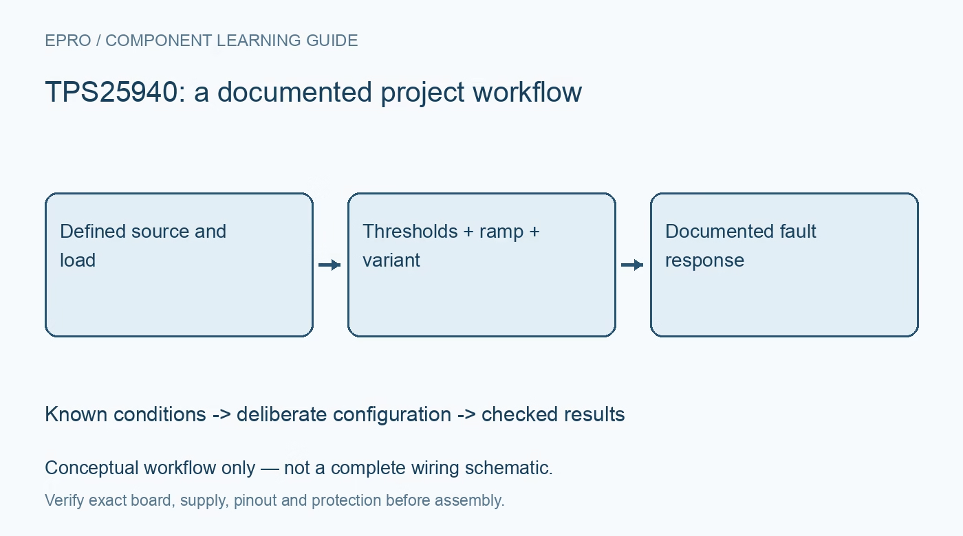
Plan TPS25940 eFuse behavior with the correct A or L variant, current and voltage thresholds, startup ramp, reverse blocking and fault recovery. This is a documentation-based planning guide, not a report of independent hands-on testing.
1. Identify the TPS25940 recovery variant
The shared documentation covers TPS25940A and TPS25940L with different recovery behavior for documented fault conditions. Confirm the exact variant and carrier before deciding whether a thermal shutdown should lead to automatic retry or a latched-off state. Neither policy is universally preferable. Record what the application should do after a fault and how an operator or controller establishes that the cause has been removed. A short product title is not a complete protection specification. Manufacturer documentation.
2. Define the source and protected load
List source voltage variation, available fault energy, wiring capability, load profile and output capacitance. Keep recommended operating conditions distinct from absolute maximum ratings. An eFuse adds configurable protection functions but does not certify an arbitrary installation as safe. Use a suitably bounded low-voltage setup for introductory evaluation and preserve appropriate independent safeguards. Do not demonstrate protection by creating uncontrolled shorts, high-energy discharges or other hazardous faults in connected equipment. Manufacturer documentation.
3. Calculate voltage-supervision thresholds
Use the documented undervoltage and overvoltage configuration relationships with component tolerances and source variation. Define which supply conditions should permit the load to operate and which should inhibit it. Keep threshold calculations with the resistor network and board revision. A nominal divider value alone does not establish exact transition points. Analyze marginal-source behavior so repeated enable and disable cycles are not mistaken for a mysterious communications or load failure elsewhere in the system. Manufacturer documentation.
4. Set current limit with thermal consequences
Choose the documented current-limit setting for both the intended load and the complete power path. Include startup demand and the device dissipation during limiting, not just conduction loss in ordinary operation. A current-limited output can still involve substantial energy and heating. Do not use thermal shutdown as a normal regulator mode. Preserve the limit calculation, external component and source capability together so the protection policy remains understandable after a hardware substitution or firmware change. Manufacturer documentation.
Newest in the store


5. Review startup ramp and reverse blocking
Select the documented output-ramp arrangement with output capacitance and downstream startup requirements in mind. Assess reverse-current blocking in the actual circuit, including any load-side storage or alternate source. A feature list does not establish that every path through a finished assembly is protected. Do not directly join unknown sources to test reverse behavior. Analyze the complete power tree and define the expected input and output conditions before proposing a controlled evaluation sequence. Manufacturer documentation.
6. Interpret monitor and status outputs correctly
Review the current-monitor scale and the documented power-good and fault behavior for the chosen configuration. Check required pull-ups and host input limits before connecting diagnostics. A status indication is not an independent precision measurement, and a current-monitor reading should retain its specified uncertainty. Record the fault context rather than clearing indications automatically without investigation. Some protections and supervision conditions have different timing, so a single generic fault label may hide information needed for useful diagnosis. Manufacturer documentation.
7. Validate recovery without claiming universal safety
Keep variant, thresholds, current limit, ramp, source, load and diagnostic behavior with the evaluation record. Verify only through controlled procedures and appropriate equipment within the intended operating boundary. Component recognition or manufacturer compliance information does not automatically transfer to a complete product. The linked LM66100 article covers a different power-path function, not equivalent protection policy. This TPS25940 guide proposes documented fault-handling checks and claims no independent fault-injection results or certification of an arbitrary protected system. Manufacturer documentation.
Related reading: LM66100 Ideal Diode: 7 Checks for a Controlled Power Path.
Catalog note: The exact-part search did not return a matching Epro listing during preparation. Check the current catalog; this guide makes no price, availability or included-accessory claim.