


FDC1004 Capacitive Sensor: 7 Checks Before Level Estimates

FDC1004 Capacitive Sensor: 7 Checks Before Level Estimates
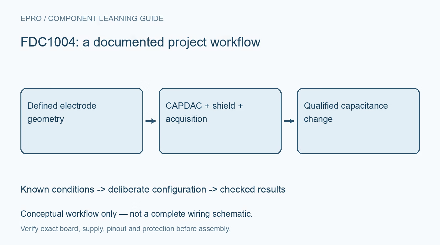
Plan FDC1004 capacitive sensing with defined electrodes, CAPDAC offset, driven shielding, coherent data and application-specific level calibration. This is a documentation-based planning guide, not a report of independent hands-on testing.
1. Define the FDC1004 physical sensor
FDC1004 converts capacitance-related measurements through a configurable input arrangement. It does not directly report a universal distance, liquid level or moisture percentage. Electrode geometry, surrounding conductors, material properties and installation conditions influence the result. Start with a drawing of the sensing electrode, reference or return arrangement and the object being observed. Record the intended physical change so later software can be evaluated against a defined sensor rather than an unexplained changing number. Manufacturer documentation.
2. Check the actual electrical arrangement
Review the supply and logic requirements of the IC and the exact carrier before connecting a host. A board that accepts a particular power input may still expose signal levels requiring separate analysis. Keep sensing electrodes and external connections within the documented limits. This is not an isolated interface for hazardous liquids or energized equipment. Use a protected low-voltage evaluation and suitable mechanical separation rather than treating capacitive coupling as automatic electrical safety. Manufacturer documentation.
3. Separate offset cancellation from signal range
The device supports CAPDAC offset handling alongside a bounded measurement range. Configure it using the expected baseline capacitance and the documented relationships. Offset cancellation helps position a signal within the useful range; it does not make arbitrary capacitance measurable or calibrate level automatically. Record CAPDAC with each measurement configuration. If that setting changes, account for the change in the reconstructed quantity instead of presenting the resulting numerical jump as a physical change in the target. Manufacturer documentation.
4. Design the shield as an active connection
FDC1004 provides driven-shield outputs for documented sensing arrangements. They are not interchangeable with ordinary ground connections. Review the supported shield loading, electrode layout and intended input configuration before attaching cables or large conductive structures. A shield can influence the electric field as well as interference behavior. Do not assume that adding more shield metal always improves a sensor. Preserve the shield geometry and routing when comparing measurements or applying a calibration created on another assembly. Manufacturer documentation.
Newest in the store


5. Read the configured measurement coherently
Associate each result with its configured input or measurement slot, rate and completion state. Follow the documented multiregister read arrangement and numerical conversion rather than treating a convenient word as a complete engineering value. Preserve raw data and configuration while evaluating the driver. A repeated or partially assembled observation should be flagged instead of smoothed into the display. Communication success does not establish that the selected measurement actually corresponds to the intended electrode pair. Manufacturer documentation.
6. Characterize environmental and mechanical effects
Evaluate how container material, nearby objects, humidity, temperature, cable movement and grounding affect the actual installation. A level model developed for one liquid or container should not be assumed valid for another. Establish any calibration using known controlled conditions and retain the physical reference points and procedure. Automatic baseline removal can conceal a real slow change, so decide explicitly whether the application needs absolute condition tracking or only short-term change detection. Manufacturer documentation.
7. Report capacitance evidence before a derived level
Keep electrode and shield geometry, input configuration, CAPDAC, rate, environment and timestamps with observations. Derive a level or presence decision only within the evaluated physical boundary and flag conditions outside it. The related soil-moisture guide illustrates another capacitive application, not a matching sensor equation or wiring diagram. This FDC1004 workflow is documentation-based and claims no independent liquid-level accuracy, universal material compatibility or safety certification for electrodes installed in an arbitrary tank or process. Manufacturer documentation.
Related reading: Capacitive Soil Moisture Sensor: 7 Buying Checks.
Catalog note: The exact-part search did not return a matching Epro listing during preparation. Check the current catalog; this guide makes no price, availability or included-accessory claim.