


LM66100 Ideal Diode: 7 Checks for a Controlled Power Path

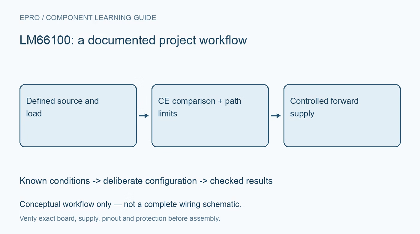
LM66100 Ideal Diode: 7 Checks for a Controlled Power Path
Plan an LM66100 ideal-diode path with correct CE comparator behavior, reverse-current boundaries, source ORing and realistic thermal limits. This is a documentation-based planning guide, not a report of independent hands-on testing.
1. Define the LM66100 power-path role
LM66100 is an ideal-diode device intended to provide a controlled low-loss power path within its documented operating range. It is not a voltage regulator, charger or complete battery-protection system. Identify which source feeds which load and which reverse-current condition must be prevented. Draw the full power tree, including alternate sources and signal-connected equipment. This makes it possible to evaluate the device function without attributing unrelated conversion or charging behavior to it. Manufacturer documentation.
2. Check direction and electrical limits
Confirm VIN, VOUT, ground and the exact carrier orientation before applying power. Review recommended operating conditions independently from absolute maximum and reverse-voltage survival specifications. A stress rating is not a normal working condition or permission to improvise a reversed-battery experiment. Keep evaluation in a protected low-voltage arrangement with a suitable current limit. A connector that physically fits does not establish polarity, voltage compatibility or the ability of the source to support the connected load. Manufacturer documentation.
3. Understand the CE comparator behavior
The enable arrangement compares CE with the input voltage according to the documented thresholds and hysteresis. Do not treat CE as an arbitrary fixed-threshold digital enable copied from another load switch. Review the intended connection and voltage relationships throughout startup, shutdown and source changes. The chosen CE network is part of the power-path function. Record it explicitly so a later board revision cannot silently change which conditions permit or inhibit forward conduction. Manufacturer documentation.
4. Interpret reverse blocking in the exact circuit
Analyze reverse-current prevention using the manufacturer connection examples and operating conditions. Do not assume that a protection feature blocks every possible path through a complete assembly. Other supplies, signal pins or components can bypass the intended route. Document the state of both source and load during evaluation. A voltage observed on an unpowered connector may require a whole-system investigation rather than a conclusion based solely on the ideal-diode part name or one nominal specification. Manufacturer documentation.
Newest in the store


5. Distinguish ORing from source priority
The documented two-device ORing arrangement can support selection behavior based on the input conditions, but it should not be described as an unrestricted programmable priority controller. Determine which source is expected to feed the load and whether the resulting rail remains acceptable during changes. Never parallel unknown supplies directly as an experiment. Where the application needs explicit source priorities or additional supervision, analyze those requirements separately instead of assuming that two ideal-diode paths provide every power-multiplexer feature. Manufacturer documentation.
6. Check loss, temperature and fault protection
On-resistance depends on conditions, and conduction loss increases with current. Assess voltage drop and heating at the intended source voltage and load using the exact package and board thermal situation. Do not treat a maximum current rating as a promise of acceptable temperature on any carrier. Provide appropriate independent protection for the source, wiring and load. An ideal-diode function alone is not evidence of comprehensive short-circuit limiting or complete battery fault management. Manufacturer documentation.
7. Record transitions and the finished power tree
Retain source identities, CE arrangement, load profile, wiring, thermal assumptions and observation conditions with the evaluation. Use suitable instruments for transition behavior rather than inferring it from a steady multimeter reading. The related converter-selection guide highlights a separate regulation function, not an equivalent replacement device. This LM66100 article proposes documented power-path checks and claims no independent reverse-polarity stress tests, unlimited source compatibility or certification that every connected system path is protected. Manufacturer documentation.
Related reading: Buck Boost Converter: 7 Checks Before Choosing.
Catalog note: The exact-part search did not return a matching Epro listing during preparation. Check the current catalog; this guide makes no price, availability or included-accessory claim.