


TMAG5170 Hall Sensor: 7 Checks for a Defensible Angle

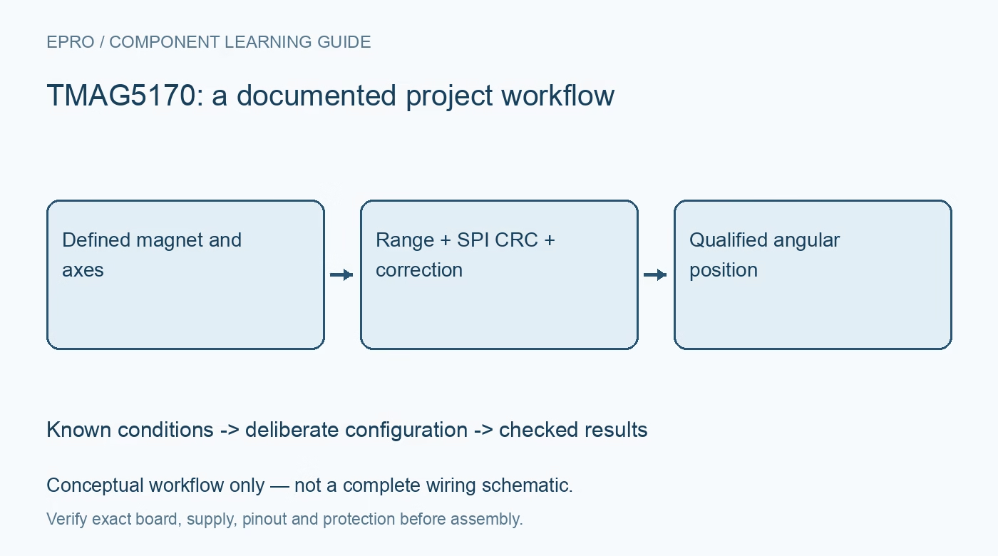
TMAG5170 Hall Sensor: 7 Checks for a Defensible Angle
Plan TMAG5170 position sensing with the correct range variant, magnet geometry, SPI CRC, coherent axes and documented angle correction. This is a documentation-based planning guide, not a report of independent hands-on testing.
1. Define the TMAG5170 mechanical geometry
TMAG5170 measures magnetic-field components along three axes and includes an angle-calculation engine. A useful angle result depends on the magnet and sensor geometry, not just the presence of three channels. Define the rotation axis, magnet position, air gap and sensor orientation before configuring the device. Distinguish angular position in a designed magnetic assembly from geographic compass heading or unrestricted three-dimensional orientation. Those applications do not become equivalent because each involves magnetic data. Manufacturer documentation.
2. Select the exact range variant
The device ordering options support different magnetic ranges. Confirm the full part and carrier before choosing range constants or assuming a library example matches the installed sensor. Select axis ranges using the expected field across the intended motion, including tolerances and alignment variation. A larger range can avoid clipping but changes the scale and useful resolution. Preserve range and axis configuration with data so a later hardware or software change cannot silently alter the physical meaning of the result. Manufacturer documentation.
3. Establish the documented SPI and CRC mode
Check supply, logic, clocking and command framing against the exact device documentation. When CRC is enabled, use the specified coverage and calculation for the configured communication. Treat an integrity failure as an invalid transaction or controlled retry rather than accepting a plausible field value. A host controller reporting transfer completion does not demonstrate correct peripheral interpretation. Preserve device identification and relevant configuration readback before evaluating mechanical angle behavior. Manufacturer documentation.
4. Acquire axes and diagnostics deliberately
Select the conversion scheme and enabled measurements according to the required motion response. Associate accepted axis data with the appropriate completion state and timestamp. Use the documented diagnostic information and distinguish it from ordinary measurement bits. A fast serial read is not proof of a fresh complete vector. Keep raw fields during evaluation so stale observations, framing mistakes, clipping and actual changes in magnetic geometry can be investigated separately instead of hidden behind a calculated angle. Manufacturer documentation.
Newest in the store


5. Configure the angle plane and correction
The angle engine uses the selected pair of magnetic axes. Choose that pair to match the mechanical arrangement and review the documented gain and offset correction facilities. A circular numeric output does not prove that offset, amplitude mismatch or mounting error has been addressed. Establish correction from a defensible procedure and retain its assembly context. Do not copy calibration constants from an unrelated magnet or assume that on-chip angle calculation eliminates the need to analyze the field trajectory. Manufacturer documentation.
6. Evaluate the full motion and field envelope
Assess the intended angular range, direction conventions and wraparound behavior alongside the measured fields. Check sensitivity to air-gap changes, nearby ferromagnetic parts, temperature and other magnetic sources. Retain the mechanical conditions with any comparison to a position reference. A smooth rotation plot can still contain systematic angle error or a reversed coordinate convention. Independent safeguards remain necessary where a position error could produce hazardous motion; a sensor diagnostic alone does not certify the control system. Manufacturer documentation.
7. Keep the acceptance record reproducible
Store part variant, range, conversion mode, communication integrity, selected angle axes, correction settings and magnet geometry with evaluation results. Flag observations outside that boundary instead of extrapolating calibration silently. The linked TMAG5273 guide discusses related geometry questions on another interface and device, not interchangeable commands. This TMAG5170 workflow is documentation-based and claims no independent encoder comparison, universal angular accuracy or safety certification simply because an integrated Hall sensor provides an angle register. Manufacturer documentation.
Related reading: TMAG5273 Magnetic Sensor: 7 Checks for Reliable Angle Experiments.
Catalog note: The exact-part search did not return a matching Epro listing during preparation. Check the current catalog; this guide makes no price, availability or included-accessory claim.