


TMP1826 Temperature Sensor: 7 Checks for an Identified Bus

TMP1826 Temperature Sensor: 7 Checks for an Identified Bus
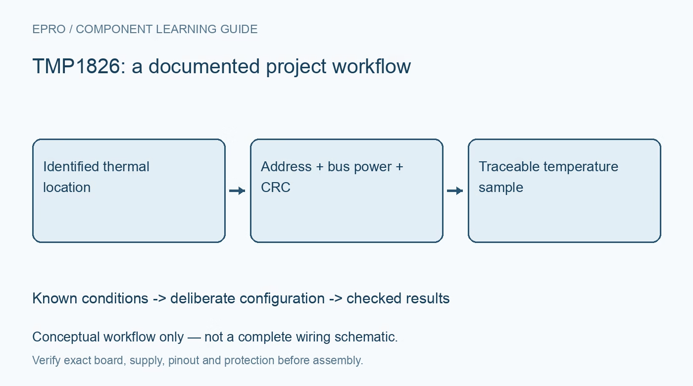
Plan TMP1826 temperature acquisition with device identity, one-wire timing, bus-power requirements, CRC validation and deliberate EEPROM handling. This is a documentation-based planning guide, not a report of independent hands-on testing.
1. Define the TMP1826 measurement location
TMP1826 is a digital temperature sensor with a one-wire-compatible interface, unique identity and EEPROM features. Define which physical location each device is supposed to represent before planning a multidrop installation. Sensor temperature, nearby board temperature and freely exposed air temperature are not automatically identical. Record package, mounting and heat paths. A long bus containing several responding devices is useful only when each accepted reading remains associated with the intended thermal location. Manufacturer documentation.
2. Identify devices rather than relying on order
Use the documented identity and addressing mechanisms to associate each installed sensor with a stable application label. Discovery order is not a dependable location identifier after reconnecting or replacing devices. Validate identity data with the specified integrity information and preserve the mapping outside a temporary display session. Do not assume that a generic one-wire temperature example uses the correct family commands. Protocol compatibility does not make every sensor family’s scratchpad and configuration layout interchangeable. Manufacturer documentation.
3. Review supply-powered and bus-powered operation
Determine whether the exact carrier uses a dedicated supply or the documented bus-powered arrangement. Check pull-ups, voltage, timing and power requirements during conversion and programming with the complete wiring and device population. A data line that reaches a valid idle voltage does not prove that it supplies every operation correctly. Include cable and connector effects in the assessment. Do not improvise a power arrangement from an unrelated one-wire device simply because the connector uses the same number of wires. Manufacturer documentation.
4. Respect timing and data-integrity requirements
Implement the documented reset, presence, addressing and transaction timing for the selected speed. Use CRC checks for the applicable identity and data structures rather than accepting any response of the expected length. Preserve a failed check as an invalid transaction or controlled retry. A plausible temperature does not establish that the correct sensor was selected or that the response is intact. Keep raw frames available during evaluation to separate electrical timing problems from interpretation errors. Manufacturer documentation.
Newest in the store


5. Decode fresh temperature data deliberately
Follow the documented conversion sequence, readiness behavior and temperature-word representation for the selected configuration. Do not reuse a resolution or sign-handling routine from another family without checking the actual data format. Associate the result with device identity and acquisition time. Polling or rereading a scratchpad does not necessarily create a new thermal observation. Include physical settling when comparing sensors, since digital conversion completion does not show that two differently mounted devices have reached the same temperature. Manufacturer documentation.
6. Separate ordinary reads from EEPROM changes
Treat nonvolatile programming, protection settings and any short-address configuration as deliberate maintenance operations. Follow the manufacturer programming requirements and retain the intended stored state with the device mapping. Avoid unnecessary writes in a routine acquisition loop. A replacement sensor can require a new identity mapping even if it receives the same application label. Configuration or identity storage should not be confused with an independently established calibration of the completed thermal installation. Manufacturer documentation.
7. Keep the bus and thermal boundary reproducible
Record device identities, package variants, power arrangement, timing, integrity outcomes, configuration and placement with evaluation results. Review accuracy conditions for the actual package instead of quoting one favorable number across all situations. The related TMP126 article concerns SPI acquisition, not interchangeable bus transactions. This TMP1826 workflow proposes documentation-based checks and claims no independent cable-length validation, thermal-chamber results or certified system accuracy merely because multiple sensors return temperatures on a shared bus. Manufacturer documentation.
Related reading: TMP126 SPI Sensor: 7 Checks for a Traceable Thermal Warning.
Catalog note: The exact-part search did not return a matching Epro listing during preparation. Check the current catalog; this guide makes no price, availability or included-accessory claim.