


LDC0851 Inductive Switch: 7 Checks for a Repeatable Threshold

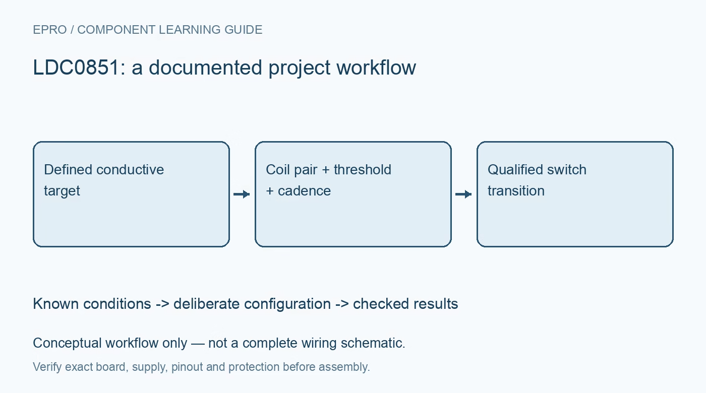
LDC0851 Inductive Switch: 7 Checks for a Repeatable Threshold
Plan LDC0851 contactless switching with matched sensing and reference coils, conductive-target geometry, threshold adjustment, hysteresis and output handling. This is a documentation-based planning guide, not a report of independent hands-on testing.
1. Define the LDC0851 switching objective
LDC0851 is an inductive comparator intended for contactless switch applications using a sensing coil and a reference coil. It does not directly provide a digital distance measurement through I2C. Define whether the project detects presence, counts events or recognizes a mechanical position. Record target material, size, orientation and travel. A switch transition can support an application decision only within a defined physical arrangement; it is not a universal measurement of how far away every metal object is. Manufacturer documentation.
2. Design the coil pair deliberately
Use the manufacturer guidance for the sensing and reference arrangement rather than selecting two visually similar coils without checking their electrical and physical relationship. Coil geometry, component characteristics, layout and nearby conductive structures influence behavior. Preserve the actual assembly in the design record. A reference coil can help with common influences, but it does not eliminate every possible environmental or mechanical difference. Replacing a coil or moving a surrounding metal bracket requires renewed assessment of the switching boundary. Manufacturer documentation.
3. Review target coupling and installation
Evaluate the conductive target through the intended range of positions and tolerances using a suitably protected low-voltage setup. Check whether the reference sensor is influenced by the target or surrounding structures in an unintended way. A bare-board demonstration near a loose metal object is not equivalent to a mounted enclosure or rotating mechanism. Do not assume that behavior established for one target material transfers unchanged to another object merely because both are conductive. Manufacturer documentation.
4. Set threshold adjustment from the documented method
Review basic operation and the documented adjustment arrangement before choosing external components. Record the intended switching condition and the installed threshold-setting network. Do not treat a resistor value as an independently calibrated distance specification. Component tolerances and the actual coil-target relationship remain part of the result. A stable transition in one convenient position is not enough evidence to choose a threshold for the full mechanical tolerance range or for conditions after final assembly. Manufacturer documentation.
Newest in the store


5. Distinguish hysteresis from universal noise immunity
Internal hysteresis supports reliable switching near a threshold, but it does not guarantee that every vibration, electrical disturbance or target variation is ignored. Identify both approach and retreat behavior with the intended geometry. Preserve those transition conditions rather than reporting only one distance. Application-level debounce or event qualification may still be relevant. Excessive filtering can hide real events, so choose it from the intended motion and required response rather than simply making an output trace look quiet. Manufacturer documentation.
6. Match cadence and output handling to motion
Select the documented enable and sampling behavior according to how quickly the target can move through the detection zone. A slow observation cadence can miss a short event even when the static threshold is repeatable. Review the push-pull output and host voltage compatibility rather than assuming an open-drain interface. Define startup and shutdown behavior for the application. A host interrupt configuration should not treat an unspecified power-transition edge as proof that a real target has passed. Manufacturer documentation.
7. Preserve the physical acceptance boundary
Keep coil pair, target geometry, surroundings, threshold setting, cadence, output polarity and event policy with observations. Use controlled physical references before making range or repeatability claims. The linked LDC1612 guide describes a different inductive acquisition architecture, not matching outputs or a direct substitute. This LDC0851 workflow proposes documented switch evaluation and claims no independent distance testing, universal immunity to contamination or certification that a contactless threshold alone provides a safe machine-position interlock. Manufacturer documentation.
Related reading: LDC1612 Inductive Sensor: 7 Checks Before Reporting Distance.
Catalog note: The exact-part search did not return a matching Epro listing during preparation. Check the current catalog; this guide makes no price, availability or included-accessory claim.