


INA186 Current Amplifier: 7 Checks for Small-Current Signals

INA186 Current Amplifier: 7 Checks for Small-Current Signals
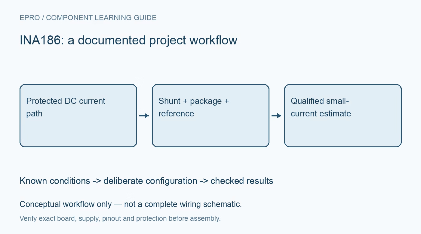
Plan INA186 current sensing with the correct gain and package, input-bias context, shunt burden, reference arrangement, ADC range and enable timing. This is a documentation-based planning guide, not a report of independent hands-on testing.
1. Define the INA186 analog chain
INA186 is a low-power analog current-sense amplifier. It does not contain a digital current register or make the host ADC unnecessary. Draw the shunt, amplifier, reference arrangement and ADC as a complete measurement chain. Define current direction and the intended range before choosing constants. Low input bias can help with small-current measurement, but it does not by itself establish finished-system accuracy or remove the influence of offset, leakage, wiring and the selected shunt. Manufacturer documentation.
2. Confirm gain and package capabilities
The family includes fixed-gain choices and package-dependent features. Confirm the complete part, carrier and exposed pins before assuming support for a reference input, enable control or bidirectional operation. The documented DSBGA arrangement does not provide the same bidirectional capability as the relevant other packages. Preserve these distinctions in the hardware record. A board substitution can change more than physical size, even when an otherwise familiar part number appears in a product description. Manufacturer documentation.
3. Select the shunt for burden and leakage context
Choose resistance, tolerance, dissipation and temperature behavior from the current range and acceptable voltage burden. A larger shunt signal can help one error contribution while changing the circuit being measured. At small currents, board contamination, connected instruments and alternate paths can matter. Keep sense routing distinct from load-current wiring where appropriate. Use a protected low-voltage setup and suitable independent reference equipment rather than assuming a larger resistor automatically turns the assembly into a precision microamp meter. Manufacturer documentation.
4. Establish output reference and ADC headroom
Use the documented reference arrangement where the selected package supports it. Predict output for the intended signed current range and compare that prediction with amplifier swing and ADC limits. Preserve reference voltage and ADC reference information in the conversion model. A nominal midpoint does not guarantee equal usable range in both directions. Do not hide clipping or an unsupported current direction by subtracting an arbitrary startup offset from every displayed sample. Manufacturer documentation.
Newest in the store


5. Check common mode separately from supply
The allowed input common-mode conditions are distinct from amplifier supply and output limits. Review them independently for the complete source and load arrangement. A high common-mode capability does not make the sensor electrically isolated or suitable for improvised direct-mains measurement. Keep evaluation bounded and low voltage. Define invalid or clipped results explicitly so a rail-limited ADC code is not presented as a trustworthy current beyond the established measurement boundary. Manufacturer documentation.
6. Include enable and settling behavior
Where available, use the documented enable function and timing rather than treating power-saving transitions as instantaneous measurement readiness. The ADC, reference and external filtering can add their own settling requirements. Preserve acquisition time relative to enabling or a load change. Low quiescent current is not the complete energy budget of a switched acquisition cycle. Repeatedly sampling before the chain settles can produce a convincing but systematically biased result even when the arithmetic and gain selection are correct. Manufacturer documentation.
7. Assess offset and gain independently
A known zero-current condition can help evaluate offset, but it does not establish gain or response under real load variation. Retain package, gain, shunt, reference, ADC configuration, enable timing and conditions with observations. The related INA240 article concerns another amplifier architecture and is not a replacement pinout or dynamic-response specification. This INA186 workflow proposes traceable small-signal checks and claims no independent microamp accuracy, universal bidirectional operation or complete-system performance based solely on a low-bias specification. Manufacturer documentation.
Related reading: INA240 Current Amplifier: 7 Checks Around PWM Switching.
Catalog note: The exact-part search did not return a matching Epro listing during preparation. Check the current catalog; this guide makes no price, availability or included-accessory claim.