


TPS63900 Buck-Boost: 7 Checks for Two Voltage Presets

TPS63900 Buck-Boost: 7 Checks for Two Voltage Presets
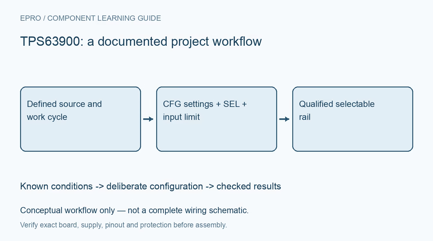
Plan TPS63900 operation with resistor-coded settings, SEL-controlled voltage changes, input current budgeting, startup behavior and bounded load transients. This is a documentation-based planning guide, not a report of independent hands-on testing.
1. Define both TPS63900 rail requirements
TPS63900 is a buck-boost converter with programmable voltage settings and dynamic selection between two presets. Define what the load requires in both states, including idle operation, active work and transitions. A lower rail can save power only if all connected circuitry tolerates it. Do not reduce the design to two attractive nominal voltages. Include processor, memory, sensor and interface requirements so voltage scaling does not quietly invalidate a peripheral or a communication path. Manufacturer documentation.
2. Verify resistor-coded configuration
Use the documented CFG resistor-selection procedure for the desired voltage presets and input-current setting. This is not an arbitrary conventional feedback-divider arrangement. Confirm the actual components on the carrier and review when configuration is read. Preserve settings and component tolerances with the board revision. A printed output label does not establish every operating option, and a software SEL change cannot compensate for hardware settings that were chosen for a different source or load. Manufacturer documentation.
3. Treat input current limit as a source budget
Review the programmed input-current behavior and its documented conditions. Input current and available output current are not the same quantity, especially as source voltage changes. A weak source may require stored energy and careful load scheduling to support bursts. Do not read a high headline output-current capability as unconditional operation under a restrictive input setting. Keep source impedance, expected load energy and the permitted rail droop together in the design assessment. Manufacturer documentation.
4. Size passive components and layout deliberately
Select the inductor and capacitors using the manufacturer guidance, including saturation, losses, effective capacitance under bias and voltage rating. Follow the recommended switching-current and sensitive-node layout practices. A long-jumper prototype is not equivalent to a compact regulator layout for meaningful ripple and transient evaluation. Keep the initial setup protected and low voltage. Independent source and wiring safeguards remain relevant even when the converter includes documented fault-protection features. Manufacturer documentation.
Newest in the store


5. Analyze startup independently of steady operation
Review the documented soft-start and current-limit behavior for the actual configuration. Include output capacitance and load behavior as the voltage rises. A circuit that operates after starting from a favorable source has not established reliable startup at the weakest intended condition. Record source voltage, impedance and load state when evaluating startup. Do not repeatedly trigger protection or brownout and then describe the resulting cycling as an ordinary low-power operating mode. Manufacturer documentation.
6. Coordinate SEL transitions with the application
Follow the documented voltage-scaling behavior and allow for the rail transition before accepting operation that needs the new voltage. Identify which tasks must pause or change frequency and how the host verifies an acceptable state. A logic-level selection signal does not prove the rail reached its target. Assess overshoot, undershoot and load interactions with appropriate instrumentation. Never assume that a sensor reading acquired during a rail transition has the same validity as one taken under settled conditions. Manufacturer documentation.
7. Evaluate complete-cycle energy and rail quality
Retain both presets, CFG components, SEL policy, input limit, source, load timing and measurement conditions with observations. Assess energy across idle, active and transition intervals rather than quoting quiescent current as battery life. The linked TPS62840 guide concerns a different step-down architecture, not matching configuration or control behavior. This TPS63900 workflow proposes bounded selectable-rail evaluation and claims no independent efficiency measurements, universal burst-load support or guaranteed energy savings from voltage scaling alone. Manufacturer documentation.
Related reading: TPS62840 Buck Converter: 7 Checks for a Low-Power Rail.
Catalog note: The exact-part search did not return a matching Epro listing during preparation. Check the current catalog; this guide makes no price, availability or included-accessory claim.