


TPS62840 Buck Converter: 7 Checks for a Low-Power Rail

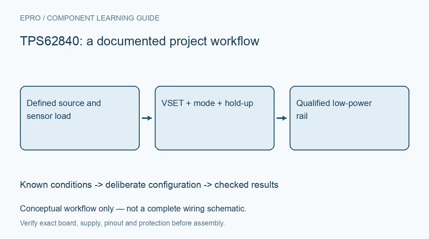
TPS62840 Buck Converter: 7 Checks for a Low-Power Rail
Plan TPS62840 regulation with resistor-selected voltage, realistic load limits, package-dependent STOP control, output hold-up and full-cycle energy checks. This is a documentation-based planning guide, not a report of independent hands-on testing.
1. Define the TPS62840 rail requirement
TPS62840 is a step-down converter intended for efficient operation with low quiescent current. Define source voltage, required rail, idle behavior and load bursts before choosing components. It does not boost a depleted source to a higher output. Review the end-of-discharge condition as well as a convenient nominal supply. A low quiescent-current figure is one part of a power budget, not evidence that every attached sensor, pull-up and processor state consumes equally little energy. Manufacturer documentation.
2. Confirm the package and available controls
The documented feature set includes package-dependent pin availability. In particular, do not assume every TPS62840 carrier exposes the STOP function. Confirm the exact ordering option, package and board connections before selecting a control strategy. Review enable, mode and voltage-selection behavior against the actual hardware. A software example for a different package can refer to a control that is physically unavailable, even when the converter name and nominal output specification appear to match. Manufacturer documentation.
3. Select voltage through the documented VSET method
Use the manufacturer resistor-selection arrangement for the available output settings rather than assuming a conventional arbitrary feedback divider. Record the installed resistor, tolerance and intended output with the board revision. Check how the configuration is established during startup and avoid casual changes during operation. Verify that the selected rail satisfies the downstream circuit throughout its operating range. A label printed on a carrier is not a replacement for checking the actual voltage-selection components. Manufacturer documentation.
4. Size the power path for bursts and startup
Choose the inductor, capacitors and layout using the documented design guidance. Include effective capacitance under bias, inductor losses, current capability and the source impedance. A maximum output-current headline does not guarantee acceptable temperature or transient behavior for every input condition. Evaluate startup and the actual burst load in a suitably bounded low-voltage setup. Do not infer regulation quality, ripple or efficiency from a no-load multimeter reading at one convenient source voltage. Manufacturer documentation.
Newest in the store


5. Distinguish operating modes from a quiet interval
Review automatic light-load behavior and forced-PWM operation for the application’s noise and energy priorities. Where the package supports STOP, understand that it temporarily stops switching rather than providing unlimited energy to the load with zero disturbance. Preserve mode selection with observations. A quiet measurement strategy must account for how the sensor, processor and converter interact; changing one mode does not automatically establish an accurate analog measurement or the lowest complete-system energy consumption. Manufacturer documentation.
6. Budget hold-up during stopped switching
Analyze load demand, capacitance and permitted voltage droop during any planned stopped-switching interval. Bound the interval and define how switching resumes before the rail becomes unsuitable. Consider capacitor tolerance, effective capacitance and real load behavior rather than relying only on a nominal stored-energy calculation. Do not describe this mode as indefinite regulation without switching. A noise-sensitive measurement taken during a collapsing supply can be less trustworthy even when the switching waveform itself is absent. Manufacturer documentation.
7. Keep energy and rail-quality evidence separate
Retain source, package, voltage setting, passive components, layout, load timing, mode and measurement conditions with evaluation data. Assess energy over the complete work cycle and examine rail behavior with suitable instruments before making performance claims. The related TPS63802 guide concerns buck-boost operation, not an interchangeable voltage-selection or STOP implementation. This TPS62840 workflow is documentation-based and claims no independent efficiency curves, universal noise-free acquisition or guaranteed battery-life improvement from the converter specification alone. Manufacturer documentation.
Related reading: TPS63802 Buck-Boost: 7 Checks Across the Battery Range.
Catalog note: The exact-part search did not return a matching Epro listing during preparation. Check the current catalog; this guide makes no price, availability or included-accessory claim.