


TPS3702 Voltage Detector: 7 Checks for a Defined Rail Window

TPS3702 Voltage Detector: 7 Checks for a Defined Rail Window
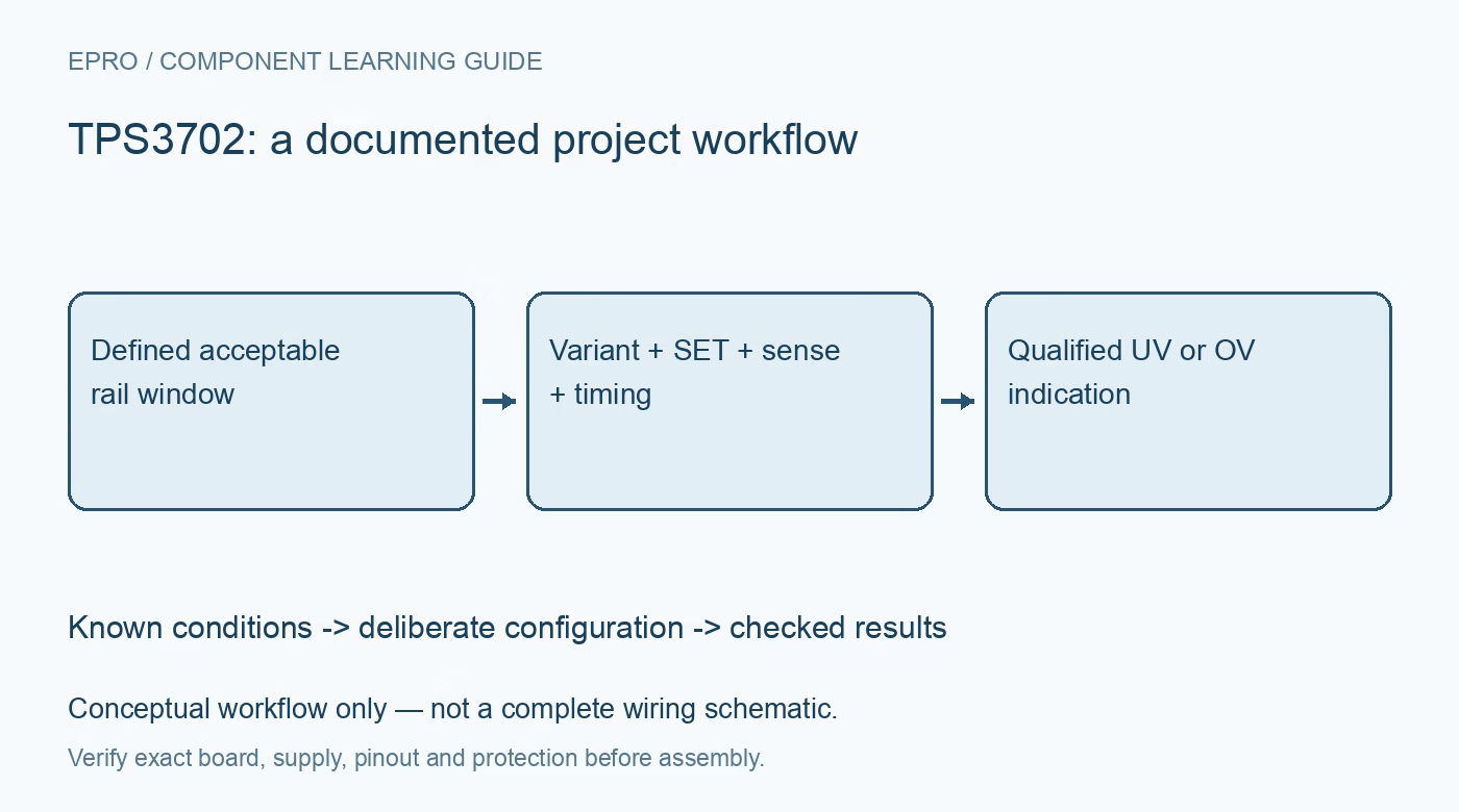
Plan TPS3702 rail supervision with the correct fixed-threshold variant, SET selection, separate supply and sense paths, open-drain outputs and timing limits. This is a documentation-based planning guide, not a report of independent hands-on testing.
1. Define the TPS3702 supervision objective
TPS3702 detects whether a monitored rail is outside a documented voltage window. It does not regulate that rail, measure precision voltage digitally or interrupt every fault current by itself. Define the downstream equipment’s permitted voltage range and the required response to under- or overvoltage. Include startup, brownout and removal of power in that policy. A fault indication is useful only when the complete system has a deliberate and suitable action associated with it. Manufacturer documentation.
2. Select the exact threshold variant
The device family uses fixed threshold arrangements associated with specific ordering options. Confirm the complete part and nominal monitored rail before choosing an application. Do not assume an arbitrary resistor divider provides the same configuration method as another voltage supervisor. Preserve the ordering identity with the acceptance window and tolerance assessment. A carrier marketed only as TPS3702 can hide threshold details that matter more to the application than the physical connector or package appearance. Manufacturer documentation.
3. Use SET according to the documented windows
The SET input selects between threshold options designed into the particular device. Review its logic requirements and intended default state rather than treating it as a continuously adjustable analog threshold control. Include threshold accuracy and hysteresis when checking the resulting window against the load requirement. An exact-looking nominal number is not the complete boundary. Record the selected state and external bias so reset, disconnection or a host startup condition cannot silently select an unintended supervision policy. Manufacturer documentation.
4. Keep supply and sense responsibilities distinct
Review the separate device supply and monitored SENSE connection for the intended circuit. Check recommended limits, grounding and behavior while either voltage is absent or changing. A monitoring feature does not authorize operation beyond pin limits or make a low-voltage device an isolated high-voltage instrument. Keep introductory evaluation protected and low voltage. Document how the supervisor remains able to provide a meaningful indication during the particular rail failure the application expects it to detect. Manufacturer documentation.
Newest in the store


5. Design open-drain output connections deliberately
Use the documented under- and overvoltage output behavior, pull-up requirements and allowed host voltage levels. If outputs are combined, preserve the loss of distinction in the diagnostic policy rather than assuming the host still knows which condition occurred. A high-impedance output is not a driven high level without the surrounding circuit. Define startup and unpowered behavior as part of the interface so an ordinary rail transition cannot become an unexplained enable or reset action. Manufacturer documentation.
6. Relate timing and hysteresis to real disturbances
Review propagation, glitch rejection and hysteresis against the application’s supply behavior and required response. Filtering can prevent unwanted indications for some transients, but it does not establish immunity to every disturbance or recognition of an arbitrarily short fault. Preserve the relevant time and voltage conditions when evaluating an event. Do not infer complete protection from a static threshold check performed with a slowly adjusted bench source and no representative downstream load. Manufacturer documentation.
7. Validate the response beyond the detector
Retain ordering variant, SET state, supply and sense wiring, pull-ups, output policy and observation conditions with results. Evaluate the actual downstream response through safe controlled procedures and suitable instruments. The related TPS25940 guide concerns an eFuse with a different power-path role, not a direct supervisor replacement. This TPS3702 workflow proposes documented rail-window checks and claims no independent transient qualification, automatic fault interruption or safety certification merely because a supervisor changes an output state. Manufacturer documentation.
Related reading: TPS25940 eFuse: 7 Checks for a Defined Protection Policy.
Catalog note: The exact-part search did not return a matching Epro listing during preparation. Check the current catalog; this guide makes no price, availability or included-accessory claim.