


ADS131M02 ADC: 7 Checks for Settled Two-Channel Samples

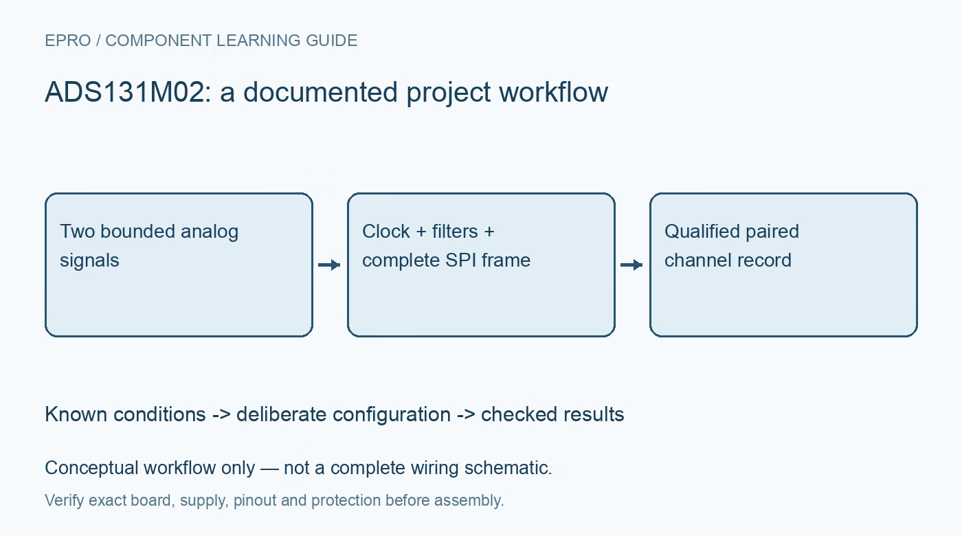
ADS131M02 ADC: 7 Checks for Settled Two-Channel Samples
Plan ADS131M02 sampling with bounded differential inputs, channel pairing, clock and gain settings, filter settling, SPI frame parsing and CRC checks. This is a documentation-based planning guide, not a report of independent hands-on testing.
1. Define the ADS131M02 channel pair
ADS131M02 contains two simultaneously sampling differential ADC channels. Define the physical meaning of both channels and their intended timing relationship before choosing software. Simultaneous sampling does not eliminate delay differences introduced by sensors, filters or wiring ahead of the ADC. Preserve channel identity and the analog signal paths in the acquisition record. A two-number result is useful only when the application knows which inputs produced it and how those signals relate to each other. Manufacturer documentation.
2. Bound every analog input independently
Review differential range, input common mode and absolute pin limits using the chosen supply and gain. An allowed differential voltage does not make an arbitrary voltage at either input acceptable. Include source loading, input filtering and protection in the design. The device is not an isolation barrier. Begin evaluation with protected low-voltage sources rather than direct hazardous-voltage wiring, even though the documentation describes metering applications that require a much broader complete-system safety assessment. Manufacturer documentation.
3. Coordinate clock, gain and filter settings
Record the reference-clock conditions, oversampling ratio, channel gains and power-related mode together. These choices influence data rate, noise and settling rather than merely changing a display scale. Use the documented transfer relationship and reference assumptions for the actual configuration. A 24-bit output format is not a promise of 24 noise-free bits in a complete circuit. Predict clipping and source requirements before adding averaging or calibration intended to improve an otherwise valid measurement chain. Manufacturer documentation.
4. Reject unsettled data after relevant changes
The manufacturer explicitly states that unsettled data are not automatically gated by this ADC. After power-up, synchronization or relevant configuration changes, the host must account for the documented filter settling time. A DRDY edge alone does not make every startup result suitable for use. Maintain a settling state and accept the appropriate subsequent sample only after the required interval. Preserve the reason for discarded data so a configuration transition cannot appear as a real physical transient. Manufacturer documentation.
Newest in the store


5. Parse the complete selected SPI frame
Implement the documented command, response, channel-word and optional CRC arrangement for the configured word length. Do not assume every serial word is a channel conversion or ignore command-response timing. Keep raw frames during driver evaluation and test signed decoding for both channels. Preserve frame and channel association rather than independently updating two values from an uncertain stream. A peripheral transfer completing at the controller establishes neither correct device framing nor a valid paired measurement. Manufacturer documentation.
6. Use CRC as an integrity check
If CRC is enabled, match the selected polynomial, initialization, word length and protected frame content to the device documentation. Reject and count failed frames instead of presenting their decoded values as ordinary readings. CRC can identify covered communication errors; it cannot establish that the analog wiring, reference or sensor calibration is correct. Include timeout and recovery behavior alongside CRC handling, and avoid silently repeating a previous valid sample when the current transaction failed. Manufacturer documentation.
7. Evaluate phase and scale beyond the ADC
Retain configuration, clock, channel mapping, raw frames, settling state and accepted-sample time with results. Channel phase or gain calibration needs suitable reference conditions and cannot remove every upstream sensor error automatically. The related ADS1256 guide covers a different converter and acquisition arrangement. This ADS131M02 workflow proposes traceable paired-sample checks. It claims no independent dynamic-range measurement, certified energy-meter accuracy or complete mains-measurement safety from simultaneous sampling and a high-resolution digital output alone. Manufacturer documentation.
Related reading: ADS1256 ADC: 7 Checks Before Trusting 24-Bit Readings.
Catalog note: The exact-part search did not return a matching Epro listing during preparation. Check the current catalog; this guide makes no price, availability or included-accessory claim.