


INA296 Current Amplifier: 7 Checks for a Bounded Bidirectional Signal

INA296 Current Amplifier: 7 Checks for a Bounded Bidirectional Signal
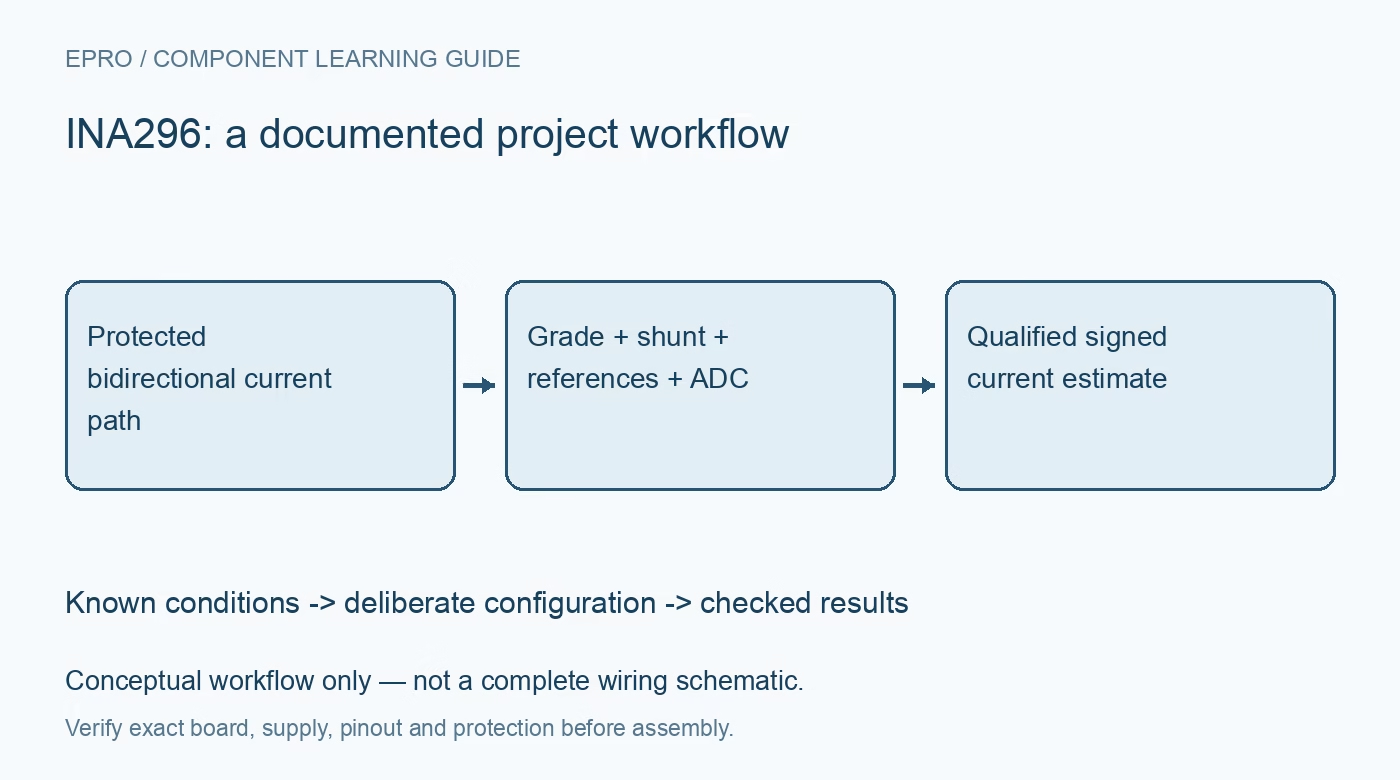
Plan INA296 current sensing with the correct A or B grade, fixed gain, dual reference pins, shunt burden, output headroom and dynamic-response limits. This is a documentation-based planning guide, not a report of independent hands-on testing.
1. Identify the INA296 grade and gain
The INA296A and INA296B family includes different precision grades and several fixed-gain options. Record the complete ordering code before selecting error limits or conversion constants. Do not combine an A-grade accuracy figure with a B-grade component or infer gain from package appearance. This is an analog current-sense amplifier, not an I2C current monitor. The host still requires an appropriate ADC and a complete transfer model for the installed shunt, references and output path. Manufacturer documentation.
2. Separate common-mode limits from supply limits
Review input common mode, differential input, amplifier supply and output limits independently. The documented operational range and the broader survival ratings have different meanings; surviving a condition does not promise a valid measurement there. High common-mode capability is not galvanic isolation. Use a protected low-voltage evaluation arrangement and suitable independent instruments. A successful analog-output reading does not establish that a circuit is appropriate for direct mains, hazardous battery systems or another high-energy application. Manufacturer documentation.
3. Choose the shunt as measurement hardware
Select shunt resistance, tolerance, power rating and temperature behavior from the intended current range and permitted burden. Keep high-current routing separate from the sense connection where appropriate. For a numerical example, a 5-milliohm shunt at 1 ampere produces 5 millivolts; gain 50 makes the signal contribution 250 millivolts. Those values illustrate arithmetic, not a tested design. Include dissipation, self-heating and layout before assigning a complete-system current accuracy to that calculation. Manufacturer documentation.
4. Connect both reference pins deliberately
Use the documented REF1 and REF2 connection options to establish the desired output reference. Do not leave one pin arbitrary or assume that any midpoint arrangement yields the same effective reference and usable range. Predict output for both current directions and check amplifier swing, ADC input limits and reference-source behavior. A nominal midpoint does not guarantee symmetrical headroom. Preserve the reference arrangement in hardware documentation so a board substitution cannot silently reverse or rescale the measurement interpretation. Manufacturer documentation.
Newest in the store


5. Budget offset and gain separately
A known zero-current condition can help investigate offset, but it cannot establish gain over the measurement range. Include amplifier grade, shunt tolerance, reference uncertainty, ADC behavior and temperature in the error assessment. At small differential signals, an apparently modest offset can dominate the current estimate. Do not force every startup observation to zero unless the actual current condition is known. Preserve uncorrected data and the assumptions behind any deliberate calibration or software compensation. Manufacturer documentation.
6. Evaluate the required transient response
Bandwidth, slew rate and settling describe different aspects of response. Assess the actual common-mode transitions, signal steps, filtering and ADC sampling schedule for the application. A headline bandwidth does not guarantee an accurate result immediately after every switching edge. The complete path can include additional delay and clipping. Compare dynamic behavior using suitable low-voltage test arrangements and instruments before applying the result to fast protection or a control loop with demanding timing requirements. Manufacturer documentation.
7. Preserve configuration with current records
Retain grade, gain, shunt, supply, reference connections, ADC configuration and observation timing with results. Define clipped, unsettled and unavailable states rather than extending the numerical scale beyond the established boundary. The linked INA240 article concerns a different amplifier architecture, not equivalent transient behavior or pin connections. This INA296 guide proposes documentation-based current-sensing checks and reports no independent accuracy measurement, switching-transient qualification or safety certification of a finished current-monitoring system. Manufacturer documentation.
Related reading: INA240 Current Amplifier: 7 Checks Around PWM Switching.
Catalog note: The exact-part search did not return a matching Epro listing during preparation. Check the current catalog; this guide makes no price, availability or included-accessory claim.