


FDC2214 Capacitive Sensor: 7 Checks Before Reporting Capacitance

FDC2214 Capacitive Sensor: 7 Checks Before Reporting Capacitance
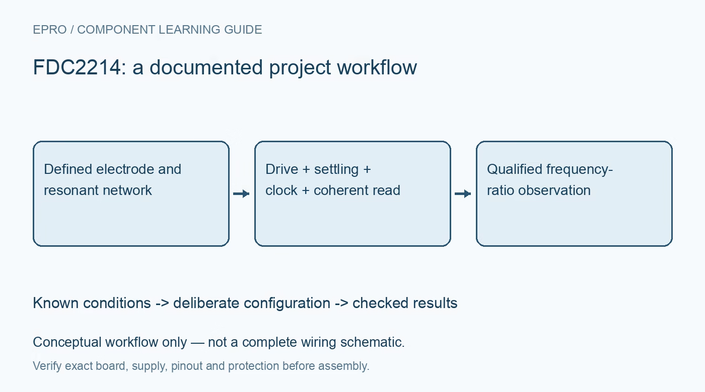
Plan FDC2214 sensing with a defined LC network, suitable excitation, clock and settling settings, coherent 28-bit reads and a justified capacitance model. This is a documentation-based planning guide, not a report of independent hands-on testing.
1. Define the FDC2214 sensing network
FDC2214 uses resonant sensing circuitry and digitizes a relationship between sensor frequency and a reference. It is not a universal capacitance meter that reports an arbitrary connected component directly in farads. Define the electrode, inductor, fixed capacitance, wiring and intended physical target. Record installation geometry and shielding. A moving cable, hand or enclosure change can alter the response independently of the target the application actually intends to detect. Manufacturer documentation.
2. Keep family and channel capabilities distinct
The family document covers different channel counts and resolution arrangements. FDC2214 provides four channels with the documented high-resolution result format; do not apply a faster lower-resolution relative’s data parsing or headline output rate. Multi-channel operation sequences channels rather than creating four identical simultaneous observations. Preserve the active-channel configuration and timing. A display with four values is not evidence that each value represents the same instant or an independently calibrated physical capacitance. Manufacturer documentation.
3. Choose resonance and clock settings together
Review sensor frequency, reference source and channel divider limits for the actual LC network. The output is related to a frequency ratio, so an incorrect reference assumption changes the derived quantity. Include inductor characteristics and parasitic capacitance in any conversion model. A familiar resonance equation can help planning only when its assumptions fit the actual network. Do not use it to claim absolute capacitance accuracy without independent characterization of the completed assembly and its relevant environmental behavior. Manufacturer documentation.
4. Set drive from the real oscillation amplitude
Use the documented drive-current configuration and recommended sensor-amplitude conditions for the installed circuit. More drive is not automatically more useful sensitivity. An unsuitable amplitude can compromise the observation even when digital communication works. Review any special high-current mode restrictions before using it. Verify the resonant behavior with appropriate low-voltage measurement methods that account for probe loading; attaching an instrument can itself change a sensitive network, so preserve the observation arrangement in the evaluation record. Manufacturer documentation.
Newest in the store


5. Account for activation and conversion intervals
Channel settling and conversion settings determine when the resonant circuit and digital result are suitable for use. Include channel-switching overhead in the complete scan interval rather than multiplying a single-channel headline rate by four. Preserve timing with target motion or liquid-level changes. A host that reads rapidly can obtain stale observations or compare differently aged channels. Define readiness, timeout and invalid-result policy explicitly instead of treating every successful register transfer as a new accepted measurement. Manufacturer documentation.
6. Read the split result coherently
Follow the documented order: read the channel’s DATA_CHx information first, then its DATA_LSB_CHx field to maintain coherency. Extract the 28-bit result without incorporating status bits as signal. Preserve watchdog, amplitude and range information according to the read-to-clear rules. A plausible number assembled from mismatched updates can conceal a driver defect. Keep raw words during development and reject invalid results rather than smoothing them into a stable-looking physical estimate. Manufacturer documentation.
7. Calibrate the physical interpretation separately
Retain LC components, geometry, reference, drive, timing, raw result and validity with derived capacitance, proximity or level information. Target material, contamination and temperature deserve their own assessment. The linked LDC1612 article concerns inductive sensing, not an interchangeable capacitance model. This FDC2214 workflow proposes documentation-based resonant-sensing checks and reports no independent femtofarad accuracy, universal distance calibration or reliable liquid identification from a high-resolution digital response alone. Manufacturer documentation.
Related reading: LDC1612 Inductive Sensor: 7 Checks Before Reporting Distance.
Catalog note: The exact-part search did not return a matching Epro listing during preparation. Check the current catalog; this guide makes no price, availability or included-accessory claim.