


INA238 Power Monitor: 7 Checks Before Integrating Power

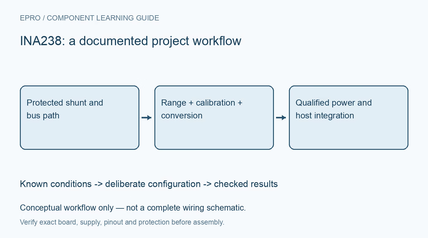
INA238 Power Monitor: 7 Checks Before Integrating Power
Use the INA238 with documented shunt scaling, register widths and conversion timing, then define a separate host-side method if the project needs energy totals. This is a documentation-based planning guide, not a report of independent hands-on testing.
1. Define the electrical boundary first
Draw where the shunt sits, which bus voltage the monitor observes and which direction represents positive current. The device supports high common-mode voltage, but it does not provide galvanic isolation. Build and troubleshoot with a protected, current-limited low-voltage arrangement before considering higher-energy systems. Check connector, conductor and shunt ratings as a complete path. A monitor surviving its specified voltage range does not make the rest of the installation safe. Manufacturer documentation.
2. Match the shunt range to the physical resistor
The selectable shunt ranges are approximately plus or minus 163.84 millivolts and plus or minus 40.96 millivolts. Their corresponding conversion scales differ, so the same raw register cannot be decoded with one universal factor. Use the actual shunt resistance, including its tolerance and expected heating, when selecting range and current scale. Check peak differential voltage and dissipation, not just nominal operating current. Preserve the range selection with each configuration record. Manufacturer documentation.
3. Establish calibration before accepting current
Select CURRENT_LSB and calculate SHUNT_CAL using the manufacturer procedure for the chosen range, shunt and intended current span. A register write succeeding is only a communications check; compare the read-back settings and a known load before accepting engineering units. Keep the signed current convention explicit. A zero calibration register can also produce zero reported power, which must not be mistaken for evidence that a physically connected circuit is consuming no energy. Manufacturer documentation.
4. Decode each register by its own format
The power result is an unsigned twenty-four-bit register, while several other measurement registers are sixteen bits and use their own signed or unsigned interpretation. Do not reuse a two-byte current helper for every result. Verify byte count, byte order, sign extension and scale individually against the register map. Include test vectors around zero and expected full scale. Truncating a valid power transaction can yield a stable-looking but fundamentally wrong value. Manufacturer documentation.
Newest in the store


5. Make conversion readiness a deliberate policy
Conversion and averaging settings determine when a complete result becomes available. Use the documented conversion-ready behavior rather than assuming that every polling cycle produces a fresh measurement. Reading DIAG_ALRT clears the relevant ready flag, so background diagnostics can affect the acquisition logic. Record which task owns that read. Also recognize that the internal current and bus conversions are sequenced; the reported power is not a promise of perfectly simultaneous external voltage and current snapshots. Manufacturer documentation.
6. Keep host energy calculations separate
The INA238 does not provide the energy and charge accumulators found in some other monitors. If energy is needed, integrate accepted power samples in the host using measured time intervals and a documented numerical method. Define what happens during resets, missing samples, saturation and long scheduling delays. Store units and sign policy with the total. Do not label a simple sum of power-register values as watt-hours without the required time weighting and conversion. Manufacturer documentation.
7. Validate the complete record under load changes
Compare voltage, shunt drop, current and power against suitable reference measurements at several safe loads. Exercise a load step, reverse current where the circuit allows it, and a communications interruption. Retain raw values, calibration, averaging settings and timestamps so unexpected totals can be investigated. Include shunt temperature and reference-instrument limitations in the uncertainty discussion. A useful qualification record distinguishes electrical error, timing error and missing data instead of hiding all three in one energy number. Manufacturer documentation.
Related reading: INA229 Power Monitor: 7 Checks for Traceable SPI Energy Records.
Catalog note: The exact-part search did not return a matching Epro listing during preparation. Check the current catalog; this guide makes no price, availability or included-accessory claim.