


TMP235 Analog Sensor: 7 Checks for Slope, ADC Reference and Settling

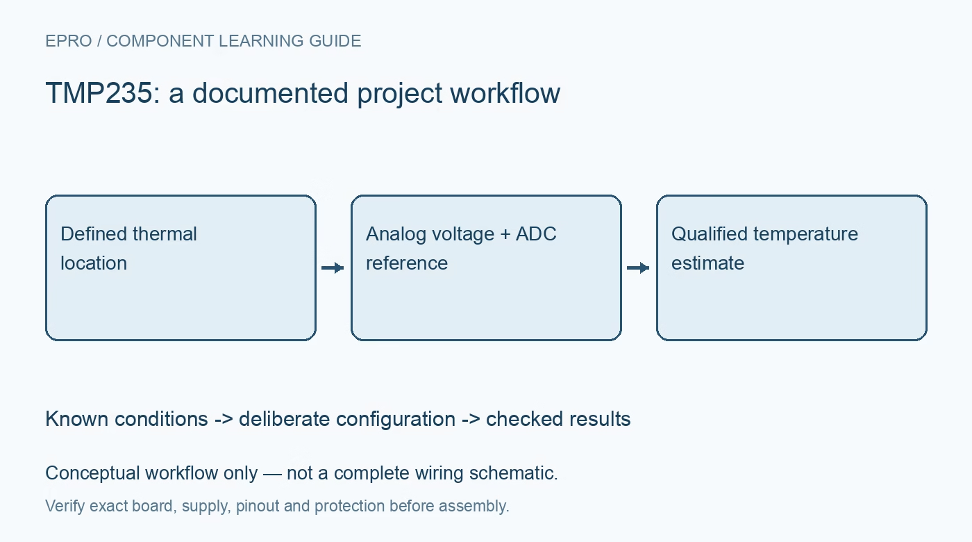
TMP235 Analog Sensor: 7 Checks for Slope, ADC Reference and Settling
Convert TMP235 output into temperature with the correct nominal slope and offset, ADC reference, capacitive loading and thermal settling checks. This is a documentation-based planning guide, not a report of independent hands-on testing.
1. Keep TMP235 and TMP236 transfer functions separate
The shared datasheet covers two analog temperature sensors with different nominal transfer functions. TMP235 uses 500 mV at zero degrees Celsius and a 10 mV-per-degree slope; TMP236 uses a different offset and slope. Confirm the installed part and accuracy grade before implementing conversion software. These devices output a voltage, not a digital temperature word. Record supply requirements, package and intended temperature range from the correct part’s specifications rather than mixing convenient figures across the family. Manufacturer documentation.
2. Define what temperature the package should represent
An analog output does not remove the need for thermal placement. The package responds to its local thermal environment, including board conduction, nearby heat sources, airflow and enclosure effects. Choose a location that represents the intended measurement and explain any expected difference from remote air or a hot component. Allow adequate stabilization when comparing against a reference thermometer. Keep self-heating and local power activity in the review instead of treating every observed temperature change as a sensor error. Manufacturer documentation.
3. Use the nominal equation with explicit units
For TMP235, the nominal conversion is temperature in degrees Celsius equals output voltage minus 0.500 V, divided by 0.010 V per degree Celsius. Convert ADC codes into voltage using the actual ADC transfer definition first, including its range, reference and coding convention. Avoid mixing millivolts with volts in the same expression. Test software with synthetic values at zero and several other temperatures. The nominal equation does not remove sensor accuracy limits, ADC errors or reference uncertainty from the result. Manufacturer documentation.
4. Treat the ADC reference as a measurement input
The sensor output is not automatically made accurate by using its supply voltage as the ADC reference. Determine the ADC reference value, tolerance and behavior during operation, then include those errors in the temperature budget. Check the complete output range against ADC limits and acquisition settings. A stable sensor supply and a changing ADC reference can still produce an apparent temperature shift. Preserve reference conditions alongside temperature logs, especially when using a battery-powered controller or a shared noisy supply. Manufacturer documentation.
Newest in the store


5. Respect the total capacitive load budget
The datasheet discusses sampled ADC loading and specifies a total capacitive-load limit of 1000 pF. Include the filter capacitor, multiplexer capacitance and ADC sampling capacitance in that total. The example filter arrangement is a starting point, not permission to add an arbitrary large capacitor. Evaluate any series resistance and the ADC acquisition interval together. A sampled input takes short charge pulses, so a quiet no-load voltage reading does not establish that every conversion has settled accurately. Manufacturer documentation.
6. Budget power-on and acquisition settling separately
TMP235 has a specified startup behavior, with an 800-microsecond typical power-on time in the headline information. Typical timing is not a guaranteed universal wait for every duty-cycled assembly. Include supply ramp, sensor settling, any output filter and ADC acquisition requirements in the enable-to-sample schedule. Discard or flag samples until the complete chain is ready. Increasing the software averaging count cannot repair a systematic acquisition error caused by sampling an unsettled analog output after each power cycle. Manufacturer documentation.
7. Validate the complete voltage-to-temperature chain
Apply controlled temperature conditions within the intended operating range and compare against a suitable reference after stabilization. Record raw ADC codes, computed voltage, reference value, sensor grade and final temperature rather than retaining only a rounded display number. Separate offset, slope, repeatability and thermal-placement effects when investigating disagreement. This planning guide does not claim independent calibration data. Revisit the acquisition checks after changing ADC settings, filter components, power timing or board location, even when the conversion equation is unchanged. Manufacturer documentation.
Related reading: HDC2022 Humidity Sensor: 7 Checks for Protected, Unheated Readings.
Catalog note: The exact-part search did not return a matching Epro listing during preparation. Check the current catalog; this guide makes no price, availability or included-accessory claim.