


TCA9539 GPIO Expander: 7 Checks for RESET and Safe Reinitialization

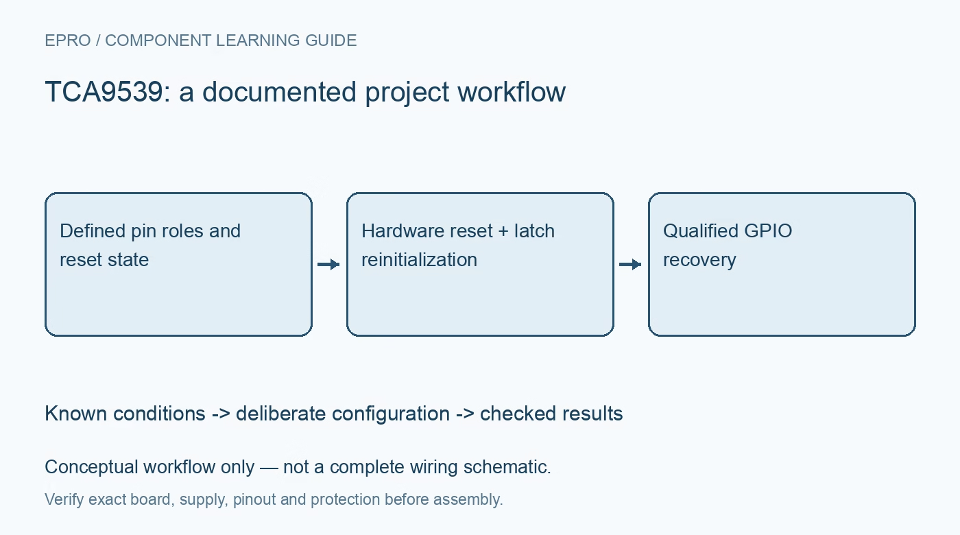
TCA9539 GPIO Expander: 7 Checks for RESET and Safe Reinitialization
Plan TCA9539 GPIO recovery around its hardware RESET pin, two address straps, external input bias and deliberate output-latch reinitialization. This is a documentation-based planning guide, not a report of independent hands-on testing.
1. Identify the reset-capable expander and its address pins
TCA9539 expands I2C into two eight-bit GPIO ports and includes an active-low hardware RESET input. It has two address-selection pins, allowing four hardware addresses, rather than the three address pins found on some related expanders. Confirm the exact package and board wiring before importing an existing pin map. An apparently similar connector or register arrangement does not establish interchangeable reset or addressing behavior. Record every port bit, load polarity and external default in a hardware-to-software mapping table. Manufacturer documentation.
2. Define RESET electrically, including host-off conditions
The datasheet calls for a suitable pull-up on RESET when it is not actively controlled. Check thresholds, timing and the state of the host pin during startup, sleep and loss of host power. Do not leave reset floating or presume a short accidental pulse is always ignored. Hardware reset reinitializes the device without removing its supply, so it can affect attached loads while other system components remain powered. Assess that transition as a real system event, not merely a software recovery convenience. Manufacturer documentation.
3. Expect default inputs after reset, not retained commands
Hardware reset returns the registers and bus state machine to their documented defaults. Port pins are configured as inputs after initialization, so a previous output command should not be assumed to survive. Choose external pull-ups or pull-downs where an attached circuit needs a safe level while the expander is resetting. This device does not provide the internal I/O pull-ups present in some related parts. Distinguish an externally held safe level from an actively driven expander output in the system documentation. Manufacturer documentation.
4. Reinitialize output latches before restoring directions
After reset, first restore the intended inactive output-latch values while the affected pins remain inputs, then enable the required output directions. Reconstruct the software’s configuration and output shadows from a known state rather than reusing stale assumptions. Keep downstream consequential actions disabled until physical levels are checked. Whole-port writes can affect unrelated loads, so apply a coherent update policy. A successful I2C read after RESET establishes communication, not completion of safe GPIO recovery. Manufacturer documentation.
Newest in the store


5. Keep register meanings and physical polarity separate
Input data, output latches, configuration and polarity-inversion registers have distinct purposes. Polarity inversion changes input interpretation and must not be treated as a universal output inversion setting. Verify both ports with bounded known signals and check each bit against the wiring map. Observe aggregate current and package limits when driving loads. Do not infer that a direct LED-drive capability authorizes arbitrary current on every pin simultaneously or that a software active-low label guarantees a safe electrical startup level. Manufacturer documentation.
6. Reconcile interrupts after reset and direction changes
INT is an active-low open-drain signal with port-specific input-change behavior. Follow the documented read and clear rules for the port that generated the indication; do not assume an unrelated register transaction clears everything. Direction changes and reset can alter the comparison state seen by the host. Re-establish a baseline input read and the host interrupt policy coherently after recovery. This interrupt is not a lossless counter of every fast external edge, so use suitable hardware when individual short pulses must be preserved. Manufacturer documentation.
7. Verify recovery with the real downstream circuit
Test normal startup, deliberate reset, host restart and the intended reinitialization sequence with consequential loads made safe. Record reset pulse timing, supply conditions, both configuration bytes, output latches and observed pin levels. Check that disconnected inputs retain defined levels and that the host does not act on stale cached data during recovery. This guide provides a manufacturer-based verification plan, not independent board validation. Reassess the sequence whenever reset wiring, host power states or downstream load polarity changes. Manufacturer documentation.
Related reading: TCA9535 GPIO Expander: 7 Checks for Floating Inputs and Interrupts.
Catalog note: The exact-part search did not return a matching Epro listing during preparation. Check the current catalog; this guide makes no price, availability or included-accessory claim.