


PCM1863 Audio ADC: 7 Checks for Channel Routing and Clock Identity

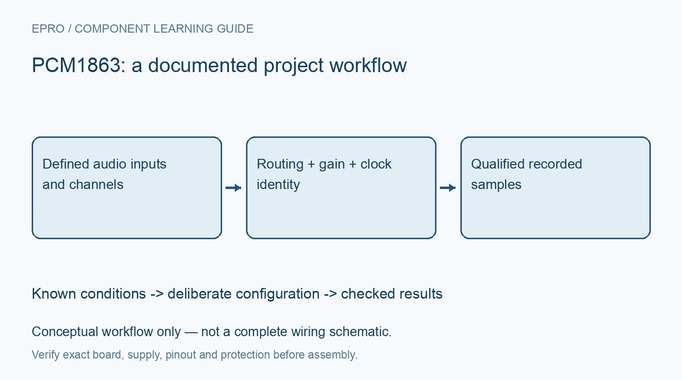
PCM1863 Audio ADC: 7 Checks for Channel Routing and Clock Identity
Bring up PCM1863 recording with the correct two-channel capability, analog routing, software control, audio clocks and verified sample framing. This is a documentation-based planning guide, not a report of independent hands-on testing.
1. Distinguish input choices from simultaneous ADC channels
The PCM186x family includes devices with different control methods and channel capabilities. PCM1863 is a software-controlled two-channel audio ADC; multiple analog input connections and routing choices do not make it a four-channel simultaneous converter. Confirm the exact device, board schematic and intended left and right signal paths. Record which physical connector reaches each selected input. A driver or application example for a four-channel family member must not be assumed to describe the installed device’s capture capability. Manufacturer documentation.
2. Match the analog connection to its intended mode
The family supports different analog input arrangements, including single-ended and differential configurations with condition-specific full-scale levels. Choose the correct mode, source return, coupling and gain for the actual signal. Do not connect a line-level source as though it were an interchangeable digital microphone or assume every input mode accepts the same voltage. Begin with a known bounded audio stimulus and conservative gain. Check the relevant electrical limits and recommended analog network before attaching an unfamiliar external source. Manufacturer documentation.
3. Establish software control without confusing it with audio transport
PCM1863 uses the applicable I2C or SPI control arrangement to configure its operation. The control bus is distinct from the serial audio interface carrying samples. Verify the selected control mode, addressing, reset state and readable configuration before enabling recording. Follow the documented register organization and page handling rather than copying bare addresses without context. A successful control transaction does not establish that the selected input mixer, ADC path or audio clocks are active and coherent. Manufacturer documentation.
4. Map routing and programmable gain deliberately
The front end includes multiplexer, mixer and programmable-gain functions. Establish one simple known route first and save its register settings before adding more complex combinations. Review whether gain changes or mixed sources can clip the analog or digital path. An apparently quiet result may come from an unselected connector, an unintended cancellation or a muted route rather than a good low-noise design. Keep channel identity, gain and source conditions together when evaluating recorded amplitude and comparing hardware revisions. Manufacturer documentation.
Newest in the store


5. Assign ownership of every audio clock
Confirm the documented clock source, PLL arrangement, sample rate and master or slave roles for the chosen configuration. The host and converter must agree on word-clock rate, bit-clock behavior and serial format. Clock detection or a status indication is useful evidence, not proof that the host interprets every slot correctly. Inspect representative clock and data timing where necessary. Do not treat a nominal sample-rate label in an operating system or audio file as independent verification of the converter’s actual acquisition clock. Manufacturer documentation.
6. Parse channels and sample words using the selected format
Set the audio interface and host capture format consistently, including word width, alignment and channel or slot assignment. Use a controlled stimulus on one input at a time to identify the returned samples. Sign handling, padding and slot offsets must follow the selected audio format; they are not inferred from the highest advertised sample rate. Preserve raw captured data during bring-up so a framing error is not hidden by automatic software gain, channel mixing or resampling elsewhere in the system. Manufacturer documentation.
7. Validate recording after startup and configuration changes
Allow the documented power, clock and signal-path settling before accepting samples after startup or a relevant configuration change. Record supply arrangement, control settings, input routing, gain, clock source and capture format with the results. Evaluate clipping, channel separation and noise using suitable controlled conditions. Headline SNR is condition-specific, not a promise for an arbitrary breakout or wiring harness. This documentation-based checklist does not report independent audio measurements and should not replace the family’s detailed application and clocking guidance. Manufacturer documentation.
Related reading: TLV320AIC3204 Codec: 7 Checks from Control Port to Valid Audio.
Catalog note: The exact-part search did not return a matching Epro listing during preparation. Check the current catalog; this guide makes no price, availability or included-accessory claim.