


TMP141 SensorPath Sensor: 7 Checks Before Accepting Temperature Data

TMP141 SensorPath Sensor: 7 Checks Before Accepting Temperature Data
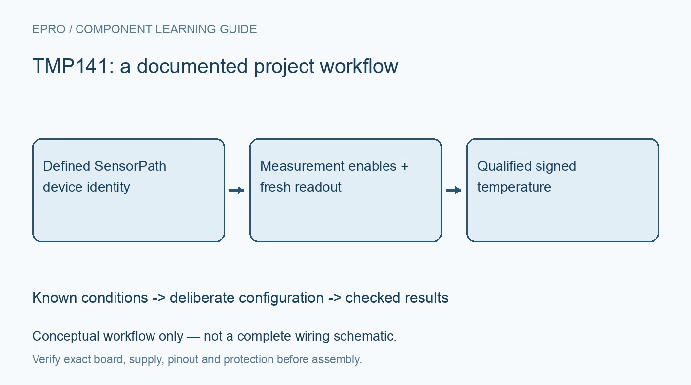
Use TMP141 correctly by verifying SensorPath timing, strapped identity, measurement-enable bits, fresh-data status and signed left-justified decoding. This is a documentation-based planning guide, not a report of independent hands-on testing.
1. Recognize SensorPath rather than a generic one-wire bus
TMP141 communicates through the single-wire SensorPath protocol. It is not software-compatible with an arbitrary one-wire thermometer, I2C sensor or the SMAART Wire UART chain used by another temperature device. Confirm that the host can generate and interpret the defined SensorPath signaling, including reset and attention behavior. Check the exact package and wiring before selecting a driver. A bus with only one data conductor is a physical description, not evidence that different manufacturers’ command sets or timing are interchangeable. Manufacturer documentation.
2. Design the open-drain bus and address straps
The single-wire data bus uses open-drain signaling and requires the specified pull-up arrangement and timing. Evaluate bus capacitance and whether the master already provides the required resistor rather than adding components blindly. The hardware address pins select one of four possible device identities; the documented device-number mapping must be used by software. Keep those pins at defined levels. Record the physical sensor location and assigned identity so a valid reading cannot silently be attributed to the wrong thermal point. Manufacturer documentation.
3. Follow reset, identification and transaction rules
Use the datasheet’s SensorPath signaling and register-access procedure rather than translating a UART or I2C transaction by analogy. Confirm identification and supported capability information before interpreting measurement registers. Handle incomplete transactions and bus reset as explicit acquisition events. A response on the wire establishes some communication, but does not establish correct device identity, a completed conversion or a supported readout format. Preserve representative raw bus traffic during bring-up so timing and addressing errors remain visible to later review. Manufacturer documentation.
4. Enable both the function and the sensor
The documented control structure separates the device-level temperature-function enable from the sensor enable in the temperature-control register. The function is disabled by default, so reading a register immediately after reset is not sufficient to demonstrate active measurement. Follow the required register writes and read back appropriate settings. Treat reserved bits according to the datasheet rather than writing arbitrary full-word patterns. Keep the conversion-rate configuration and startup interval in the acquisition plan before allowing software to publish temperature values. Manufacturer documentation.
Newest in the store


5. Decode the signed ten-bit field in the correct position
The temperature readout contains ten meaningful bits in positions fifteen through six, with a resolution of 0.25 degrees Celsius. Negative values use two’s-complement representation. Extract and sign-extend that field before applying the scale; do not treat all sixteen received bits as an independent higher-resolution temperature. Verify the decoder with synthetic positive, zero and negative values from the documented examples. The code format’s representable range does not extend the sensor’s specified operating range or guarantee its measurement accuracy. Manufacturer documentation.
6. Use freshness and overrun information explicitly
The status structure identifies completed conversions and can indicate that another conversion finished before the previous result was read. Reading the applicable result affects the documented status flags. Design polling and logging around those semantics rather than labeling every repeated register value a new sample. Repeated temperature codes can be legitimate, but identical numbers alone do not prove a conversion occurred. Record communication errors, stale intervals and overruns so a downstream system can distinguish missing acquisition from a physically steady temperature. Manufacturer documentation.
7. Validate local temperature and identity together
Apply controlled safe thermal changes and compare the correct device’s response against suitable reference equipment after stabilization. Record mounting location, airflow, supply, address straps, conversion settings and raw readout values. The package measures its local thermal condition, not automatically a remote component or ambient air temperature. Keep resolution distinct from accuracy and thermal lag. This guide provides a documentation-based acquisition checklist, not independent calibration data; repeat identity and freshness checks after bus wiring, firmware reset handling or sensor placement changes. Manufacturer documentation.
Related reading: TMP144 Temperature Sensor: 7 Checks for UART Chain Identity.
Catalog note: The exact-part search did not return a matching Epro listing during preparation. Check the current catalog; this guide makes no price, availability or included-accessory claim.