


TPS7A49 Linear Regulator: 7 Checks for NR/SS and Clean-Rail Claims

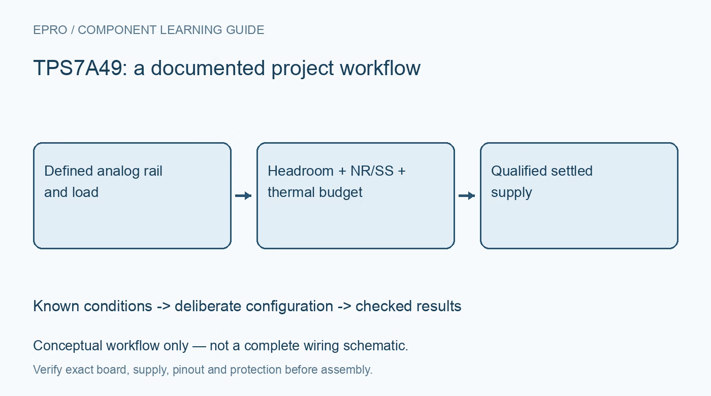
TPS7A49 Linear Regulator: 7 Checks for NR/SS and Clean-Rail Claims
Plan a TPS7A49 analog rail with adequate headroom, thermal margin, effective capacitance and deliberate noise-reduction and soft-start design. This is a documentation-based planning guide, not a report of independent hands-on testing.
1. Define the rail rather than relying on a low-noise label
TPS7A49 is a positive adjustable linear regulator intended for precision analog supplies, with a rated output capability of 150 mA under applicable conditions. Confirm the exact device, package and board schematic, then specify output voltage, load, input range and acceptable startup time. It is not a switching converter or a negative regulator. A low-noise product description does not establish the noise of the assembled rail, particularly when the source, layout and connected loads differ from the datasheet test conditions. Manufacturer documentation.
2. Budget dropout and dissipation independently
Input voltage must provide adequate headroom above the desired output while remaining within the recommended operating envelope. A typical dropout value at one current is not a guaranteed margin for every load and temperature. Separately estimate dissipation from the input-to-output voltage difference and load current, then assess the package and PCB thermal path. A regulator can have ample voltage headroom and still overheat. Begin qualification with a protected bounded source and modest load rather than interpreting the maximum input rating as a preferred operating point. Manufacturer documentation.
3. Calculate feedback and maintain a quiet sensing path
Use the manufacturer’s adjustable-output equation and resistor-selection guidance for the intended voltage. Include divider tolerance and the effect of the feedback network in the error and noise budget. Route the sensing node away from switching currents, digital edges and connector return drops. Verify the assembled resistor values before attaching sensitive analog hardware. A correct divider ratio alone does not establish load regulation at a remote connector or immunity to a noisy ground path shared with other circuitry. Manufacturer documentation.
4. Meet the effective capacitor requirements
The datasheet specifies input and output bypassing and the output capacitance required for stability. Account for actual capacitance under bias, tolerance and temperature rather than only the printed component value. Place the capacitors close to the relevant pins with suitable return paths. Do not remove the output capacitor to save space or assume that any much larger capacitor is automatically a better substitute. Evaluate startup, transient response and stability as a network including the regulator, source impedance and downstream load. Manufacturer documentation.
Newest in the store


5. Treat NR/SS as a defined analog-control connection
The NR/SS capacitor influences reference-noise reduction and soft-start behavior. Select it through the documented guidance and assess the startup delay it creates. The manufacturer cautions against resistive or inductive loading of this pin; it is not a general-purpose supply or logic output. If a feed-forward capacitor is used, follow the applicable design conditions for that network as well. Keep component choices and measurement bandwidth explicit when comparing noise results, rather than transferring a headline value to every configuration. Manufacturer documentation.
6. Separate noise, PSRR and transient measurements
Noise figures depend on integration bandwidth and circuit conditions, while PSRR varies with frequency, headroom, load and component choices. Neither is a universal fixed attenuation applied to all disturbances. Check the actual upstream ripple and downstream demand, including load transitions and startup. Use appropriate probing and instrumentation so ground loops or measurement bandwidth do not dominate the result. A stable meter reading can establish an approximate DC voltage without demonstrating low wideband noise or clean recovery from a pulsed load. Manufacturer documentation.
7. Qualify enable and settling with the real analog circuit
Keep EN at a defined level and verify normal power-up, disable and restart behavior using the intended source and load. Allow the configured soft-start and downstream settling before accepting precision measurements. Record input and output voltage, current, temperature, capacitor network, NR/SS configuration and measurement bandwidth. Protection features do not replace a sound thermal design. This documentation-based guide defines the qualification work and does not claim independent noise measurements or certify an arbitrary regulator board for a particular precision instrument. Manufacturer documentation.
Related reading: TPS7A20 Low-Noise LDO: 7 Checks for Headroom and Real PSRR.
Catalog note: The exact-part search did not return a matching Epro listing during preparation. Check the current catalog; this guide makes no price, availability or included-accessory claim.