


ADS7038 ADC: 7 Checks for Channel Identity, Averaging and CRC

ADS7038 ADC: 7 Checks for Channel Identity, Averaging and CRC
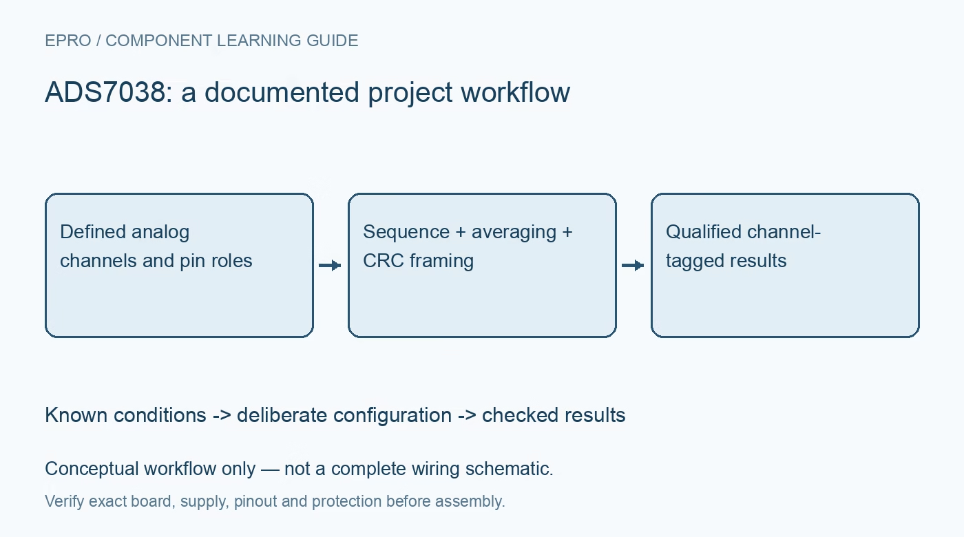
Configure ADS7038 acquisition with explicit analog or GPIO pin roles, channel identity, averaging latency and CRC-aware frames before using conversion data. This is a documentation-based planning guide, not a report of independent hands-on testing.
1. Resolve the device and every multiplexed pin role
ADS7038 is an eight-channel multiplexed twelve-bit SAR ADC, with channels configurable as analog inputs or GPIOs. The related ADS7038H has a different speed capability, so confirm the exact part rather than copying a family headline. Draw the actual pin allocation before sending commands. A connector wired for an analog sensor must not accidentally become a driven digital output. Record source voltage limits, supply arrangement and external circuitry for each pin, including channels that remain unused. Manufacturer documentation.
2. Configure analog and digital roles before starting acquisition
Use the documented pin and GPIO configuration registers to establish the intended analog inputs, digital inputs and output-driver behavior. Check register reset defaults and appropriate readback before activating connected hardware. AVDD and DVDD have separate operating requirements, and the analog scaling depends on the documented reference arrangement. Follow local bypassing and DECAP guidance. A successful register transfer does not prove safe pin direction, correct input range or an acquisition sequence that actually visits the intended channels. Manufacturer documentation.
3. Select manual or automatic acquisition deliberately
The converter supports different channel-selection and conversion arrangements, including manual selection and automatic sequencing. Follow the documented startup, offset-calibration and mode-entry procedures for the chosen operation. Preserve the enabled-channel set and sequence state in the driver. A command that selects one channel is not a promise that an arbitrary subsequent word belongs to it without considering the selected mode and frame timing. Keep acquisition boundaries explicit when changing the channel set or restarting after a reset. Manufacturer documentation.
4. Preserve channel identity in the output format
The output can append a channel ID or status field according to configuration. Select and parse the correct option instead of assuming every low-order group of bits is a channel number. The host must also agree on conversion length, optional CRC and any averaging-related format change. Test with distinct bounded levels on different inputs to verify physical-to-logical mapping. Preserve raw frames during bring-up so a sequence offset cannot be hidden by plausible-looking values from another connected sensor. Manufacturer documentation.
Newest in the store


5. Treat averaged sixteen-bit output as a filtered result
The programmable averaging function produces a sixteen-bit result, but the underlying converter remains a twelve-bit SAR architecture. Averaging adds latency and changes the time required before a completed result can be read. It does not establish sixteen-bit absolute accuracy or remove reference, offset and input-settling errors. Use the documented oversampling settings and timing, and distinguish filter output width from native conversion resolution. Record the averaging factor with each dataset, particularly when comparing transient behavior or measurement update rates. Manufacturer documentation.
6. Enable CRC coherently in both device and host
CRC support changes the required data framing and interpretation. Configure the device and host in a deliberate sequence and implement the documented polynomial, bit ordering and covered data, rather than checking an invented generic checksum. Handle configuration-write error reporting and received-data integrity separately where the protocol requires it. Reject malformed or failed-integrity frames and keep counters visible. A valid CRC establishes transport consistency for the defined frame, not correct channel wiring, analog settling or system measurement accuracy. Manufacturer documentation.
7. Validate watchdog decisions against timing and data quality
The analog watchdog includes channel thresholds, hysteresis and event-related behavior that depend on configuration and the documented comparison format. Averaging, sequence timing and event counting affect when an indication can occur. Test bounded normal threshold crossings and verify the associated channel and output status. Do not present a watchdog flag as an independently certified protection function. Save pin roles, sequence, averaging, frame format, CRC configuration and error counts with the measurements; this guide defines checks rather than claiming independent converter results. Manufacturer documentation.
Related reading: ADS8866 SAR ADC: 7 Checks for CONVST Mode and Input Settling.
Catalog note: The exact-part search did not return a matching Epro listing during preparation. Check the current catalog; this guide makes no price, availability or included-accessory claim.