


DRV8874 Motor Driver: 7 Checks for Latched Modes and Current Feedback

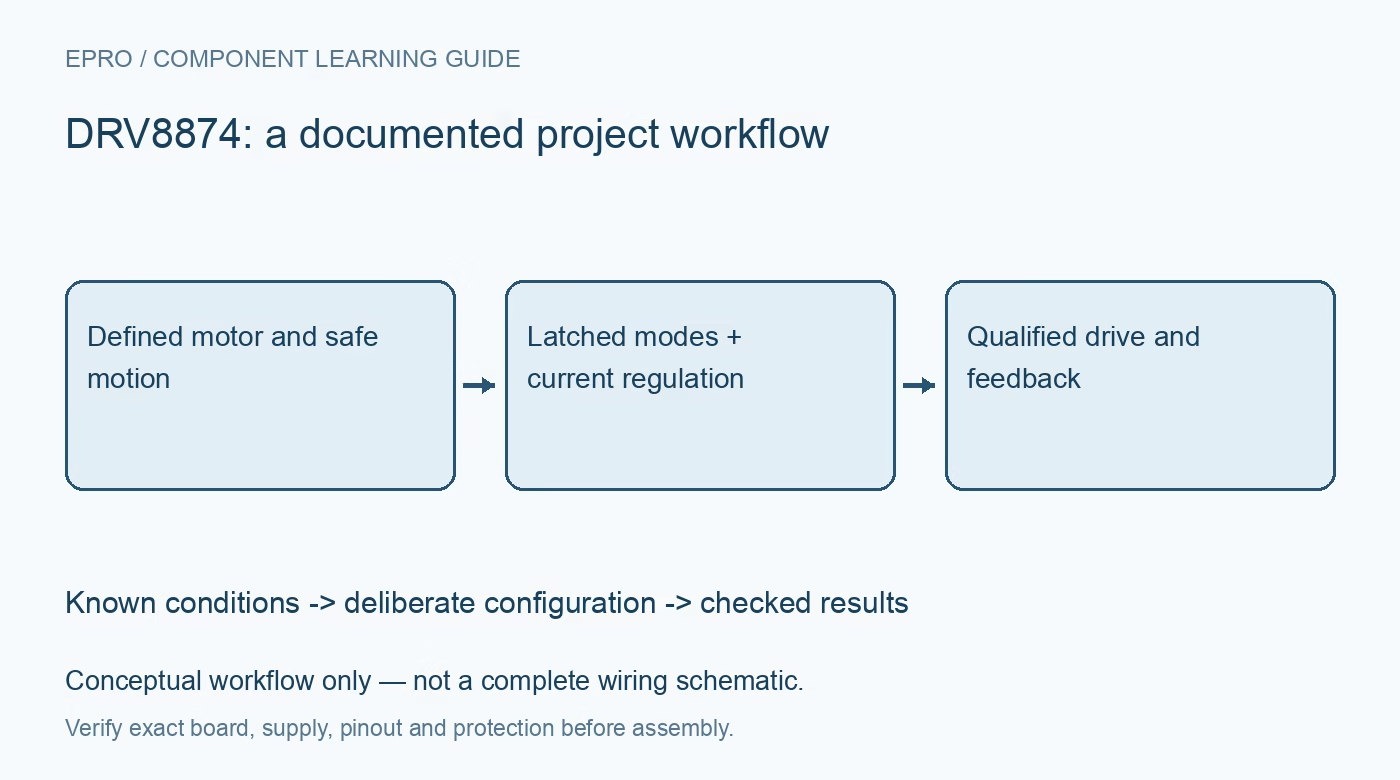
DRV8874 Motor Driver: 7 Checks for Latched Modes and Current Feedback
Configure DRV8874 motion with the correct latched PMODE and IMODE settings, current-feedback scaling and bounded startup checks before driving a load. This is a documentation-based planning guide, not a report of independent hands-on testing.
1. Identify the power stage and a safe motion envelope
DRV8874 is an H-bridge driver for a brushed DC motor or other supported load configurations. Confirm the exact part, board schematic, motor winding and mechanical travel before energizing it. The six-ampere peak headline is not a continuous-current guarantee for every board and temperature. Use a current-limited source, restrained safe motion and a practical stop method. Disconnect power before changing motor connections, and evaluate both the motor and PCB thermal limits. Manufacturer documentation.
2. Latch the intended control mode deliberately
PMODE selects the documented control arrangement, including phase-and-enable, PWM and independent half-bridge operation. Its state is captured when the driver is enabled through nSLEEP. Changing PMODE while running is therefore not a supported substitute for the specified sleep-and-reenable procedure. Define the pin level or permitted high-impedance configuration in hardware, then follow the timing requirements. Record the selected truth table so firmware does not confuse a brake command with a coast or drive command. Manufacturer documentation.
3. Treat IMODE as configuration with protection consequences
IMODE selects documented current-regulation behavior and also affects overcurrent response. Its state is latched at enable, so apply the required sleep interval and configuration sequence when changing it. Keep normal current regulation distinct from fault protection: one shapes intended load current, while the other responds to an abnormal condition. Do not assume the independent half-bridge mode retains the same internal current-regulation function; the datasheet explicitly describes different behavior for that control arrangement. Manufacturer documentation.
4. Scale IPROPI and VREF from the actual circuit
IPROPI provides a proportional current output that can be converted to voltage through an external resistor. Use the device-specific scaling and permissible voltage range when choosing that resistor and the host ADC connection. VREF participates in the current-regulation threshold, so evaluate both settings together. A larger monitor resistor is not an unrestricted way to increase measurement sensitivity. Check headroom and loading before attaching the final controller, and retain the scaling equation with the component values. Manufacturer documentation.
Newest in the store


5. Interpret feedback within the switching and load context
Current feedback depends on the driver’s documented sensing behavior and the active control arrangement. Evaluate the ADC sampling schedule, filtering and expected recirculation intervals rather than treating every instantaneous voltage as an equally representative motor-current sample. Increased current can indicate startup, mechanical load or a fault; it is not a calibrated torque or absolute-position measurement. Preserve commanded drive state and timing alongside the feedback so software can distinguish normal acceleration from an unexpected sustained condition. Manufacturer documentation.
6. Read fault indication without guessing the cause
nFAULT reports defined protection events, including supply and thermal conditions, not a universal mechanical-stall verdict. Use the selected mode’s fault and recovery rules and investigate the underlying condition before clearing or restarting repeatedly. Monitor the supply at the device during startup and ordinary load changes. Keep safe operating checks separate from destructive testing; this guide does not call for improvised hard shorts or driving an unprotected mechanism into an obstruction to demonstrate protection. Manufacturer documentation.
7. Record repeatable startup and shutdown evidence
Verify bounded forward motion, reverse motion, the intended stop state, sleep and restart using the actual motor and source. Save PMODE, IMODE, nSLEEP timing, feedback components, current limit and observed temperature conditions. Check the load voltage and motion independently of firmware commands. This documentation-based checklist does not report independent driver measurements. Reassess the mode-latching sequence and feedback interpretation whenever the motor, control mode, PCB or sampling schedule changes, even if the driver part remains the same. Manufacturer documentation.
Related reading: DRV8876 Motor Driver: 7 Checks for Useful Current Feedback.
Catalog note: The exact-part search did not return a matching Epro listing during preparation. Check the current catalog; this guide makes no price, availability or included-accessory claim.