


TPS2116 Power Mux: 7 Checks for Priority and Break-Before-Make

TPS2116 Power Mux: 7 Checks for Priority and Break-Before-Make
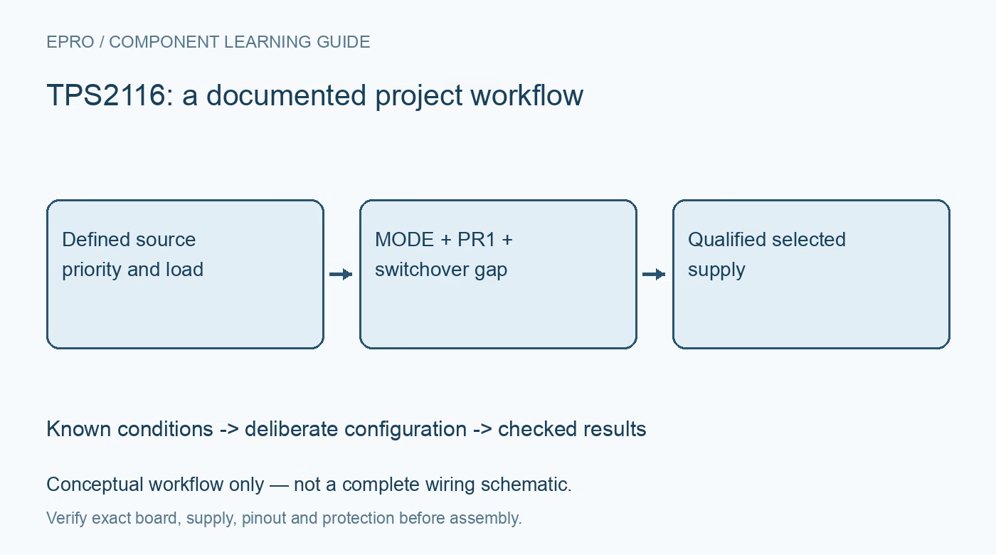
Plan TPS2116 source selection with its actual MODE and PR1 truth table, break-before-make interval, reverse blocking and qualified status interpretation. This is a documentation-based planning guide, not a report of independent hands-on testing.
1. Define source selection rather than voltage conversion
TPS2116 selects between two input supplies; it does not regulate their voltages to one fixed output. Its recommended inputs are 1.6 V to 5.5 V, with continuous-current capability subject to operating and thermal conditions. Record both source ranges, their impedance and the load’s minimum and maximum acceptable voltage. Do not infer that either battery or adapter is automatically preferred merely from which one measures higher. Source-selection policy depends on the actual control configuration and intended application. Manufacturer documentation.
2. Use the complete MODE and PR1 truth table
Priority operation ties MODE to VIN1 and monitors VIN1 through the documented PR1 divider arrangement. Manual operation uses the applicable externally biased control states. Do not simplify this into an assumed universal rule that MODE low always means priority. The table also includes shutdown and other selection behavior that must be understood for the actual wiring. Document each normal and startup control state, including host-off conditions, so a reset cannot unintentionally change which supply powers the load. Manufacturer documentation.
3. Calculate the priority threshold with tolerance
For the priority arrangement, PR1 is compared against the internal reference through the chosen divider. Calculate the intended source threshold from the manufacturer guidance, allowing for reference and resistor tolerances and the source’s behavior under load. A nominal threshold is not an exact battery state-of-charge measurement. Check that the selected backup source is actually present and within range when needed. Preserve divider values and expected switching conditions in the hardware record rather than hiding the policy inside an unexplained schematic note. Manufacturer documentation.
4. Budget the break-before-make interval explicitly
When changing channels, the device turns off the old path before enabling the new one. During that interval the output can dip according to load current, output capacitance and the relevant timing. This is not an unconditional seamless or zero-interruption supply. Evaluate the hold-up needed by the actual downstream circuit, including capacitor tolerance and voltage dependence. Observe the load voltage during representative transitions. A steady output reading before and after the event can miss a short dip that resets a processor. Manufacturer documentation.
Newest in the store


5. Account for reverse blocking and output discharge conditions
The device blocks reverse current when the output is above an input under the documented conditions. If the output is still higher than the source being selected, connection can wait until the output falls to the applicable threshold. This affects a transition from a higher-voltage source to a lower one. Check alternate paths through cables and signal interfaces as part of the system. Reverse blocking is not a battery-charging controller, nor does it guarantee that all stored output energy disappears immediately. Manufacturer documentation.
6. Interpret ST with its electrical and fault semantics
ST is open drain and needs a suitable pull-up. Its documented high and low states indicate source-related behavior, but a low state can also occur during thermal shutdown. Therefore, one status bit alone cannot prove which source is delivering a valid regulated load voltage. Check ST alongside both inputs, control pins and output during qualification. Keep the pull-up supply and host thresholds in the design review so an absent logic rail or disconnected signal is not mistaken for a valid selection decision. Manufacturer documentation.
7. Qualify ordinary source ramps and host resets
Test normal source insertion, removal, voltage ramps, control changes and host reset with protected bounded supplies. Include the datasheet’s conditions for fast source changes and the voltage available on the remaining source. Record input and output waveforms, load, capacitance, control states and status rather than only a final pass indicator. This guide describes manufacturer-based verification, not independent switchover measurements. Reassess the hold-up and selection policy when a source, load, capacitor or firmware power-state behavior changes. Manufacturer documentation.
Related reading: TPS25947 eFuse: 7 Checks for Variant, Inrush and Fault Policy.
Catalog note: The exact-part search did not return a matching Epro listing during preparation. Check the current catalog; this guide makes no price, availability or included-accessory claim.