


ADS7052 SAR ADC: 7 Checks for Previous-Sample Data and Calibration

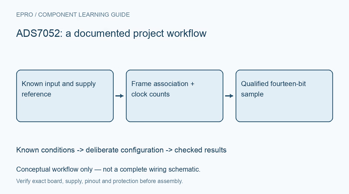
ADS7052 SAR ADC: 7 Checks for Previous-Sample Data and Calibration
Read ADS7052 correctly by mapping previous-conversion data, completing its required clock counts and distinguishing startup calibration from valid samples. This is a documentation-based planning guide, not a report of independent hands-on testing.
1. Resolve the fourteen-bit device and its input span
ADS7052 is a single-ended fourteen-bit SAR ADC with separate analog and digital supplies. Confirm the actual package and board connections rather than assuming every pin-compatible family member has the same resolution or input type. Its unipolar measurement span is tied to AVDD under the documented conditions. Record the source range, supply values and host logic levels. A driver written for a related twelve-bit converter needs a deliberate review, not just a different scale constant. Manufacturer documentation.
2. Include the analog supply in voltage uncertainty
The analog supply establishes the applicable conversion reference, so supply tolerance and noise affect the volts represented by each code. Follow local bypassing, input limits and grounding guidance. Check the physical input and its return at the converter, including transients and any filter network. Do not equate a nominal supply label with an exact measured reference. More output bits do not eliminate reference uncertainty, source error, input settling or the converter’s own offset and gain contributions. Manufacturer documentation.
3. Complete the startup calibration frame
The documented power-up offset-calibration procedure requires twenty-four serial clocks in the first transfer with chip select held appropriately. Output zeros during this process are calibration traffic, not a valid zero-input measurement. Releasing chip select too early aborts the procedure. Follow the specified clock and acquisition timing for the actual supply, then allow the required acquisition interval before proceeding. Internal offset calibration corrects an internal error term; it does not calibrate the external sensor or the complete voltage-measurement chain. Manufacturer documentation.
4. Associate returned data with the previous conversion
During normal operation, the serial clocks convert the newly sampled input while transferring data from the previous conversion. This is a crucial sample-association rule. The first returned word after startup is not automatically a newly completed physical measurement. Maintain an explicit acquisition state in the driver and align timestamps with the sampling sequence. Verify the mapping using a known controlled input pattern rather than assuming that every word belongs to the chip-select edge that immediately precedes its receipt. Manufacturer documentation.
Newest in the store


5. Verify conversion clocks and data alignment separately
The conversion requires at least eighteen clock falling edges within the frame. A short frame can make the following returned conversion invalid, even when the current received word looks plausible. Follow the timing diagram for the leading output state, fourteen meaningful data bits and remaining clocks. Do not blindly reuse another ADC’s padding or edge convention. Check the host’s actual transfer width and clock edges, then test the parser with synthetic codes and representative captured transactions. Manufacturer documentation.
6. Schedule deliberate recalibration rather than accidental long frames
The documented normal-operation calibration sequence uses sixty-four clocks and has its own data and recovery behavior. Longer transfers are therefore not universally harmless padding. Distinguish ordinary conversion frames, interrupted frames and deliberate recalibration in the driver state machine. Respect the required acquisition interval after each applicable transition. Evaluate source impedance and filtering at the fastest intended sampling cadence; a correctly framed result can still be inaccurate if the sampled analog input has not settled. Manufacturer documentation.
7. Preserve validity and scaling context with every dataset
Validate settled results at several known input levels while retaining raw frames, frame-validity state, supply values, clock count and sample association. Exclude calibration and interrupted-transfer results rather than averaging them into a dataset. Record the event that restarts acquisition after power changes. This guide is documentation-based, not independent converter characterization. Recheck timing, scaling and previous-sample alignment after changing host transfer width, burst scheduling, power cycling or the analog source network. Manufacturer documentation.
Related reading: ADS7042 SAR ADC: 7 Checks for Startup Calibration and Supply Scaling.
Catalog note: The exact-part search did not return a matching Epro listing during preparation. Check the current catalog; this guide makes no price, availability or included-accessory claim.