


TPS7A30 Negative Regulator: 7 Checks for Polarity and Enable

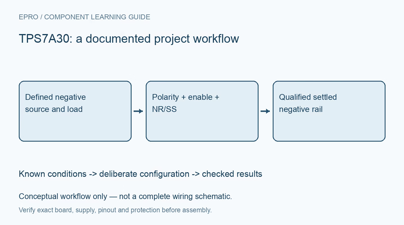
TPS7A30 Negative Regulator: 7 Checks for Polarity and Enable
Plan a TPS7A30 negative analog rail with correct supply polarity, dual-polarity enable interpretation, NR/SS design, headroom and thermal checks. This is a documentation-based planning guide, not a report of independent hands-on testing.
1. Confirm a negative regulator rather than an inverter
TPS7A30 is a negative linear regulator. It needs a suitable negative input supply; it does not generate a negative output directly from a positive battery. Confirm the package, ground reference and board schematic before making connections. Record the requested output, input range and load current. A related positive regulator may offer similar noise-reduction concepts, but its polarity, pin connections and operating equations must not be copied without checking this device’s documentation. Manufacturer documentation.
2. Evaluate negative-rail headroom and dissipation
For regulation, the negative input must provide sufficient voltage magnitude beyond the desired negative output, within the recommended operating limits. A typical dropout figure at one load is not a universal margin. Separately assess dissipation from the input-to-output voltage difference and load current, including PCB thermal performance. Adequate headroom does not prevent overheating. Begin with a protected bounded source and modest load, verifying polarity at the pins before connecting sensitive downstream analog circuitry. Manufacturer documentation.
3. Use the negative-output feedback arrangement
Calculate the output-setting network through the manufacturer’s negative-regulator equation and recommended connections. Check resistor placement, tolerance and the actual feedback node rather than informally adding minus signs to a positive-supply schematic. Keep sensing returns quiet and separate from high-current disturbances. Verify the assembled network before enabling the final load. The regulated voltage at the package and the voltage delivered through a connector can differ when return currents and trace resistance are not accounted for. Manufacturer documentation.
4. Understand the dual-polarity enable input
The documented EN function can enable the regulator with a sufficiently positive or sufficiently negative control voltage relative to ground. It must not be modeled as an ordinary positive-only logic input without checking the relevant thresholds and ratings. Choose a defined safe state for startup, host reset and loss of a control supply. Follow the manufacturer guidance for the chosen topology. An accidental negative control level is not automatically the same thing as a disabled low state. Manufacturer documentation.
Newest in the store


5. Design NR/SS and capacitors as one network
NR/SS affects noise reduction and startup timing. Select that capacitor and any applicable feed-forward network from the device-specific guidance; do not reuse the positive regulator’s timing coefficient by analogy. Meet effective input and output capacitance requirements, accounting for tolerance and voltage bias. Keep component placement and return paths consistent with the layout recommendations. A quiet DC meter reading does not demonstrate correct stability or startup behavior, and arbitrary extra capacitance is not a universal remedy for ripple. Manufacturer documentation.
6. Keep noise claims tied to measurement conditions
Output noise depends on bandwidth, capacitors, load and the complete supply arrangement. PSRR varies with frequency and operating conditions rather than acting as one constant attenuation at every disturbance. Evaluate the actual upstream negative source and representative downstream demand with suitable instrumentation. Avoid ground connections that unintentionally short or redefine the negative rail during probing. Preserve headroom, load, measurement bandwidth and the capacitor configuration when comparing results with manufacturer curves or another board. Manufacturer documentation.
7. Qualify the complete dual-rail startup if applicable
When this rail accompanies a positive supply, review the downstream circuit’s tolerance of either rail arriving or disappearing first. Verify normal enable, disable, restart and settling with the actual load made safe. Record both rail voltages, control states, current and temperature conditions. Protection features do not establish complete system safety or eliminate thermal design work. This guide defines documentation-based verification checks, not independent regulator measurements; repeat them after changing the input source, enable wiring or downstream analog circuit. Manufacturer documentation.
Related reading: TPS7A49 Linear Regulator: 7 Checks for NR/SS and Clean-Rail Claims.
Catalog note: The exact-part search did not return a matching Epro listing during preparation. Check the current catalog; this guide makes no price, availability or included-accessory claim.