


INA185 Current Amplifier: 7 Checks for Bidirectional REF Scaling

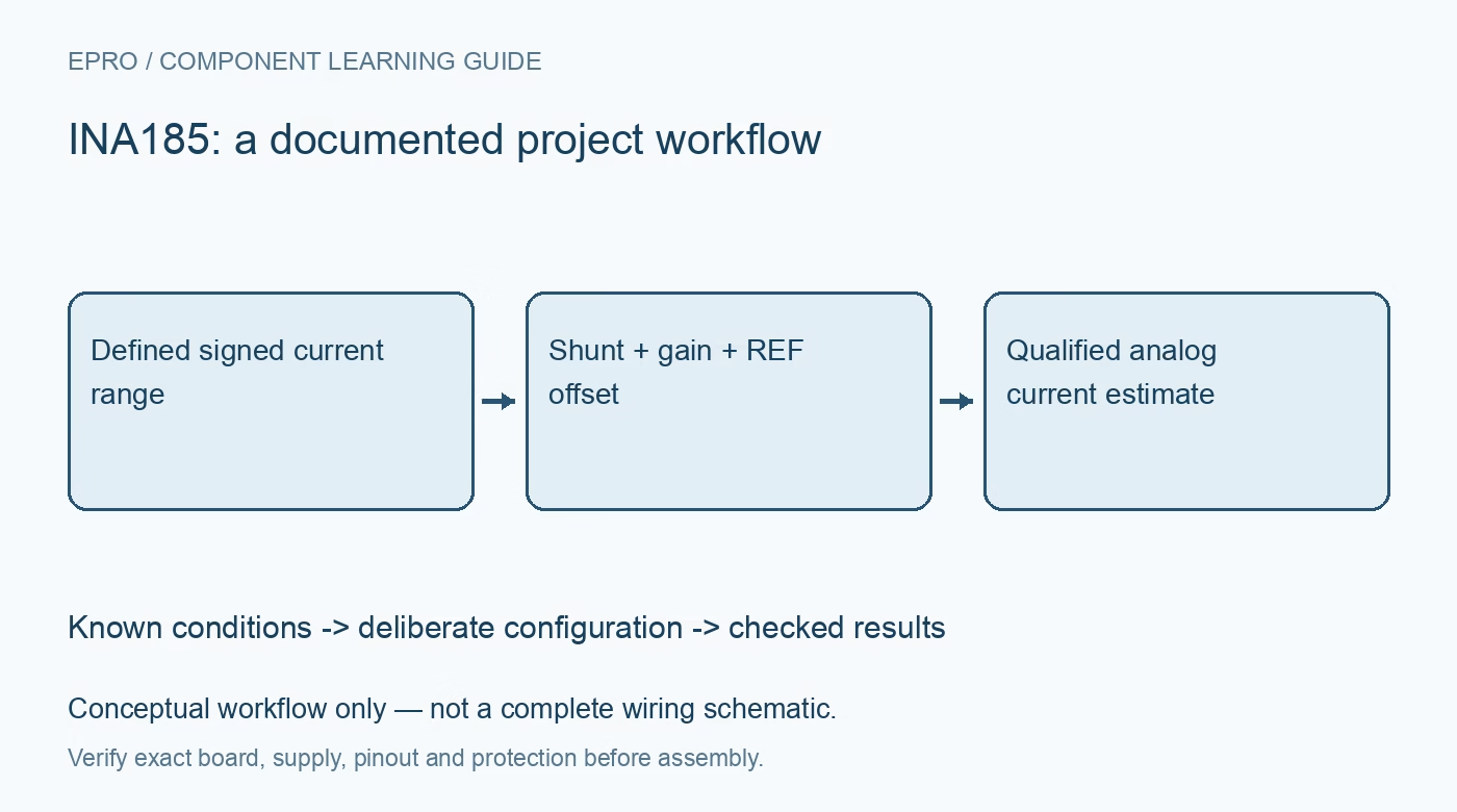
INA185 Current Amplifier: 7 Checks for Bidirectional REF Scaling
Use INA185 bidirectional current feedback with the correct gain suffix, reference offset, shunt polarity, output headroom and ADC scaling checks. This is a documentation-based planning guide, not a report of independent hands-on testing.
1. Confirm the gain variant and analog interface
INA185 is an analog current-sense amplifier with four fixed-gain options, not a digital monitor with current registers. Confirm the full suffix, package and board pinout before implementing scaling. Its bidirectional capability uses the REF connection to offset the output. Do not borrow a unidirectional amplifier’s zero-current assumption without reviewing that pin. Draw the shunt, supply, reference source and ADC connection, and define which physical current direction will be positive in the application. Manufacturer documentation.
2. Keep supply and common-mode limits distinct
The supply operates over its specified low-voltage range, while the input common-mode range extends from slightly below ground to the documented higher bus voltage. Those ratings apply to different pins and must not be interchanged. Check each input, the differential signal and the operating common-mode conditions. Begin with a protected low-voltage setup and bounded current. An allowed common-mode voltage does not authorize applying the same voltage to the amplifier supply, REF input or host ADC. Manufacturer documentation.
3. Select the shunt for signal and heating together
Choose shunt resistance from the intended positive and negative current ranges, gain and output headroom, then assess dissipation, tolerance and temperature coefficient. Use an appropriate sensing layout so trace and connector drops do not become an unexplained part of the resistance. A smaller shunt reduces heating but makes offset and noise larger relative to the signal. Preserve the gain suffix and actual resistance with the error budget rather than assuming a higher-resolution ADC can compensate for poor analog scaling. Manufacturer documentation.
4. Establish REF as a measured zero-current reference
With a suitable REF voltage, positive differential input produces output above the reference and negative differential input produces output below it. Follow the specified REF drive and loading conditions. A nominal midpoint is not automatically exact or immune to noise. Check its voltage and behavior under operating conditions, and include reference error in the signed-current calculation. A ground-referenced configuration can support a different measurement arrangement, but should not be confused with symmetric bidirectional sensing around midscale. Manufacturer documentation.
Newest in the store


5. Leave output swing for both current directions
The nominal output relationship includes reference voltage plus gain times shunt differential voltage. Evaluate both extremes against the documented output-swing limits at the selected supply and load. If one direction clips, subtracting REF in software will not recover the missing information. Test the decoder with values above and below the intended zero-current level. Include amplifier offset, gain error, shunt uncertainty and ADC reference uncertainty, especially near zero where the desired differential signal may be small. Manufacturer documentation.
6. Check filtering and sampled-ADC loading
Follow the manufacturer guidance for input filtering and source impedance rather than inserting unmatched components casually. At the output, evaluate any RC network and the ADC acquisition interval together. Headline bandwidth depends on gain and test conditions; it is not a guarantee of complete-system settling at every sampling rate. Capture representative bounded current transitions with suitable instrumentation and distinguish actual current behavior from reference movement, common-mode disturbance, output clipping or an unsettled ADC input. Manufacturer documentation.
7. Validate signed scaling against an independent reference
Compare both supported current directions and zero-current behavior against suitable reference measurements in a safe setup. Retain raw ADC codes, REF voltage, supply, gain suffix, shunt value, load and temperature conditions. Flag saturation or invalid acquisition instead of reporting an apparently precise signed number. This documentation-based guide does not claim independent amplifier characterization. Recheck both zero reference and range headroom after changing the shunt, reference driver, ADC, gain option or expected reverse-current demand. Manufacturer documentation.
Related reading: INA290 Current Amplifier: 7 Checks for Gain and Common-Mode Limits.
Catalog note: The exact-part search did not return a matching Epro listing during preparation. Check the current catalog; this guide makes no price, availability or included-accessory claim.