


INA290 Current Amplifier: 7 Checks for Gain and Common-Mode Limits

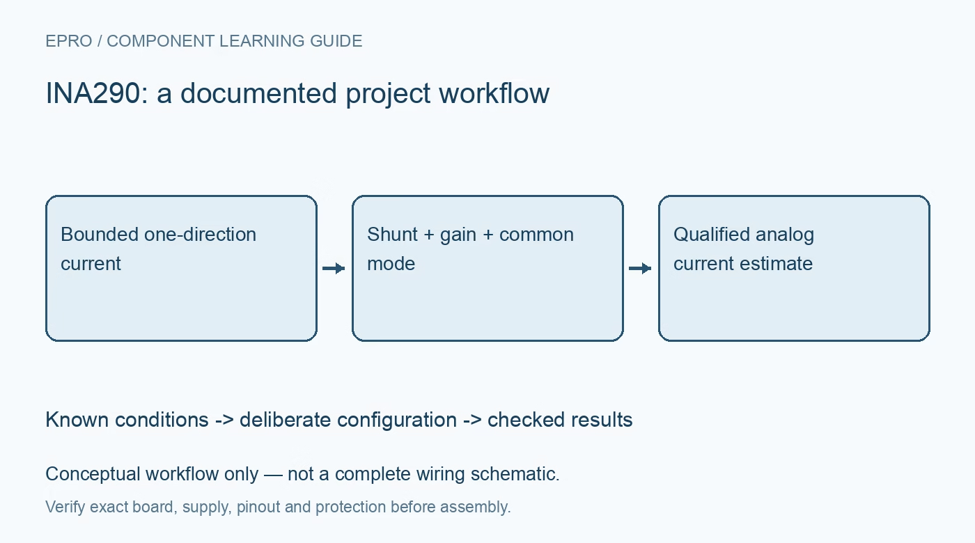
INA290 Current Amplifier: 7 Checks for Gain and Common-Mode Limits
Plan INA290 unidirectional current sensing by checking the gain suffix, shunt polarity, common-mode range, output headroom and ADC acquisition chain. This is a documentation-based planning guide, not a report of independent hands-on testing.
1. Resolve channel count and fixed gain first
The family includes single-channel INA290, dual-channel INA2290 and quad-channel INA4290, with multiple fixed gain options. Confirm the full suffix and package rather than assuming every member has the same channel count or voltage gain. INA290 is an analog current-sense amplifier, not a digital current monitor with an internal measurement register. Draw the shunt connections, supply, analog output and receiving ADC. A software scaling constant cannot repair a circuit built with the wrong gain variant. Manufacturer documentation.
2. Keep common-mode voltage separate from supply voltage
The documented operating common-mode range is 2.7 V to 120 V, while the amplifier’s own supply range is 2.7 V to 20 V. Those ranges describe different pins and must not be interchanged. Survival ratings outside normal operation do not guarantee valid measurements. In particular, a shunt near ground is not automatically within the operating common-mode range. Qualify with protected low-voltage sources first; this guide does not instruct users to work on energized high-voltage buses or bypass appropriate electrical-safety controls. Manufacturer documentation.
3. Respect unidirectional operation and shunt polarity
The manufacturer specifies unidirectional operation: current from the supply toward the load produces the intended positive shunt voltage and output response. Do not copy a bidirectional amplifier’s reference-offset equation or expect negative current to appear symmetrically around midscale. Verify IN-plus and IN-minus wiring against the actual current direction. If regeneration or reverse-current measurement is required, select a suitable topology. A clipped near-ground output is not a calibrated negative-current indication and should not be translated into one in software. Manufacturer documentation.
4. Select the shunt from signal and dissipation budgets
Choose resistance using the intended current range, fixed gain and available output swing. Then evaluate shunt heating, tolerance, temperature coefficient and power rating, including expected transients. Use Kelvin sensing where appropriate so connector and copper drops do not silently become part of the measured resistance. A smaller shunt reduces dissipation but also reduces the signal relative to offset and noise. Document that trade-off instead of assuming the lowest resistance or highest gain is always the most accurate choice. Manufacturer documentation.
Newest in the store


5. Leave output headroom at both ends of the range
The ideal relationship is output voltage approximately equals gain times shunt differential voltage for the supported direction, but the real output has finite swing limits. Check the specified load and supply conditions before converting the entire ADC range into current. Low-current behavior near the output floor needs its own assessment, as does high-current saturation. Include amplifier offset, gain error and shunt uncertainty in the budget. A high-resolution ADC cannot restore information lost when the amplifier output is already clipped. Manufacturer documentation.
6. Evaluate input filtering and ADC loading as a system
The datasheet provides guidance for input-filter networks because added impedance can affect current-sense performance. Follow that guidance rather than inserting unmatched resistors casually. At the output, check whether the amplifier and any RC network settle adequately into the ADC’s sampled input. Bandwidth and transient behavior depend on gain and conditions, not only a headline figure. Observe representative load changes with suitable instrumentation, separating real current dynamics from filtering, common-mode disturbance or acquisition-related artifacts. Manufacturer documentation.
7. Validate scaling with a known bounded current
Compare the measured output and ADC result against a suitable independent current reference at several useful points within the safe setup. Record gain suffix, shunt value, supply, common-mode voltage, output loading, temperature and ADC reference. Include zero-current behavior without assuming the output must equal an ideal zero volts. Preserve raw codes and clipping flags alongside calculated current. This documentation-based checklist does not claim independent amplifier measurements or certify a high-voltage installation; changes in gain, shunt, filtering or acquisition require renewed review. Manufacturer documentation.
Related reading: INA296 Current Amplifier: 7 Checks for a Bounded Bidirectional Signal.
Catalog note: The exact-part search did not return a matching Epro listing during preparation. Check the current catalog; this guide makes no price, availability or included-accessory claim.