


TMP123 SPI Sensor: 7 Checks for Chip-Select Conversion Freshness

TMP123 SPI Sensor: 7 Checks for Chip-Select Conversion Freshness
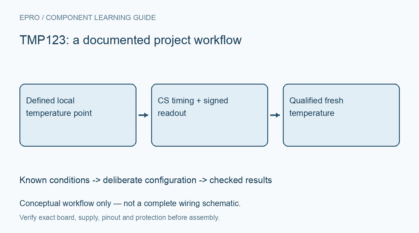
Read TMP123 temperatures with correct chip-select timing, signed-field extraction and startup handling instead of confusing repeated reads with new conversions. This is a documentation-based planning guide, not a report of independent hands-on testing.
1. Distinguish this readout sensor from a programmable relative
TMP123 shares its datasheet with TMP121 and provides SPI-compatible temperature readout. Confirm the exact package and pin assignment; related part numbers need not share the same physical arrangement. Do not import threshold-register or shared bidirectional-data commands from a different sensor family. Identify the serial-output, clock and chip-select connections explicitly. A library that receives sixteen bits is only a starting point: the measurement field, conversion schedule and startup behavior still need to match this device. Manufacturer documentation.
2. Allow conversion time while chip select is high
The sensor performs temperature conversions while CS is high. The manufacturer specifies the required conversion interval before an updated result is available. Reading more frequently does not create new independent conversions. Plan the acquisition cadence around the documented conversion and idle cycle rather than the host’s maximum SPI speed. Keep the interval available for conversion explicit in firmware, particularly when several devices share a bus or a power-saving routine changes the usual polling schedule. Manufacturer documentation.
3. Understand what pulling CS low actually does
Asserting CS low terminates a conversion in progress and places the analog circuitry into shutdown while the last completed conversion is shifted out. The returned word therefore represents the last completed measurement, not an instantaneous temperature sample triggered by that read. Repeatedly interrupting conversions can prevent fresh data from becoming available. Capture the actual chip-select waveform during qualification and distinguish a successful serial transaction from evidence that a new thermal conversion finished. Manufacturer documentation.
4. Parse the signed temperature field only
The upper thirteen bits contain signed temperature data with the documented scale, while a defined low bit and high-impedance trailing positions are not temperature information. Extract and sign-extend the correct field before applying the nominal 0.0625-degree scale. Do not interpret the entire received word as a pure sixteen-bit temperature. Verify negative, zero and positive examples from the manufacturer table using synthetic test data, because an ordinary room-temperature bench test may never expose a sign-handling error. Manufacturer documentation.
Newest in the store


5. Treat startup zero and repeated values carefully
The temperature register initially reads zero until the first conversion completes. Exclude that startup interval rather than logging it as a real zero-degree measurement. Repeated values after startup may represent a stable environment or a conversion schedule that is being interrupted; the number alone cannot distinguish them. Preserve validity state and expected update timing in the acquisition record. Power cycling and host resets should re-enter a deliberate startup sequence instead of immediately accepting the first serial word. Manufacturer documentation.
6. Separate resolution from thermal accuracy
A small digital increment is not an equivalent guarantee of temperature accuracy. Use the specified error limits for the intended temperature range and account for local mounting, board conduction, airflow and stabilization time. The package measures its own thermal condition, not automatically a remote heat source or surrounding air. Check supply and interface conditions against recommended operation. A fast clean data stream cannot correct thermal placement error or make the physical package respond faster than its actual thermal coupling allows. Manufacturer documentation.
7. Validate freshness with the complete polling routine
Compare readings against suitable reference equipment after stabilization while running the real firmware’s chip-select timing. Record conversion windows, raw words, decoded fields, supply and physical location. Test startup and the intended low-power or burst-reading schedule, not only continuous laboratory polling. This guide provides manufacturer-based checks and does not report independent calibration. Revisit conversion availability and field decoding whenever the SPI transaction wrapper, bus-sharing policy, power timing or sensor mounting changes. Manufacturer documentation.
Related reading: TMP122 SPI Sensor: 7 Checks for Shared Data and Signed Temperature.
Catalog note: The exact-part search did not return a matching Epro listing during preparation. Check the current catalog; this guide makes no price, availability or included-accessory claim.