


TPS62040 Buck Converter: 7 Checks for Light-Load Voltage Positioning

TPS62040 Buck Converter: 7 Checks for Light-Load Voltage Positioning
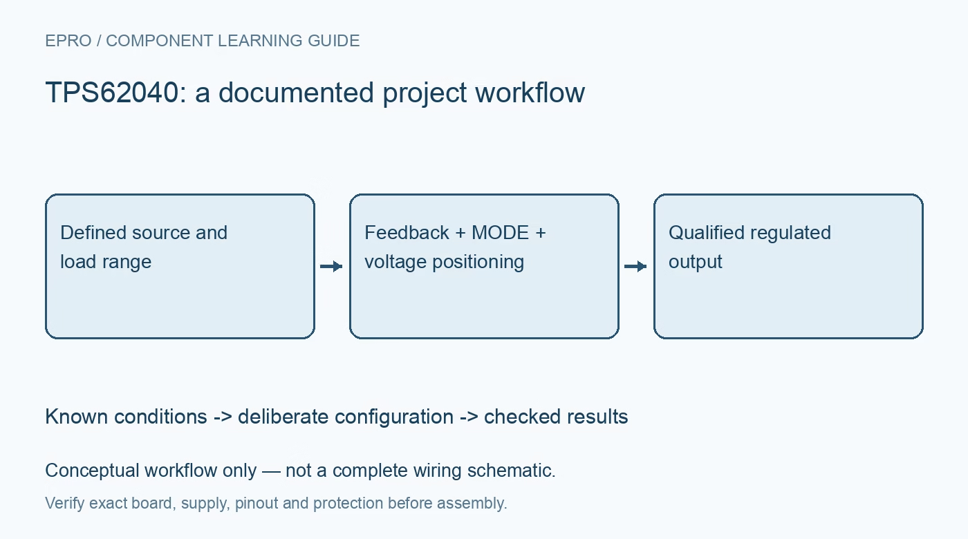
Evaluate TPS62040 regulation with its actual MODE setting, dynamic light-load voltage positioning, feedback, dropout and representative load transitions. This is a documentation-based planning guide, not a report of independent hands-on testing.
1. Identify the adjustable member and actual power stage
TPS62040 belongs to a step-down family with adjustable and fixed-output members. Confirm the complete part, package, feedback network and board components before choosing an output target. The family supports a condition-dependent load capability, not arbitrary voltage conversion at the headline current. Record source range, load profile and allowable output tolerance. As a buck converter, it cannot maintain an output above an insufficient input, regardless of a correct feedback ratio or a successful unloaded bench reading. Manufacturer documentation.
2. Select MODE for the actual application
Pulling MODE high forces the documented fixed-frequency operation; the other supported setting permits power-save behavior at light loads. Keep the pin at a defined level and document the intended policy. Changing operating mode can affect ripple, light-load voltage and efficiency, so do not compare two boards without matching that condition. A processor’s idle state or a disconnected peripheral can move the converter into a different regime even while the nominal output setting remains unchanged. Manufacturer documentation.
3. Understand intentional light-load voltage positioning
The datasheet describes power-save thresholds slightly above the nominal output target, creating dynamic output-voltage positioning at light load. A small higher no-load reading is therefore not automatically a bad divider or a failed calibration. Compare the observation with the specified operating conditions, tolerance and ripple. Conversely, do not dismiss every excessive voltage as intended positioning. Check the actual mode and waveform, and include the downstream device’s allowable supply limits before accepting the behavior. Manufacturer documentation.
4. Calculate feedback and maintain the sensing return
Use the adjustable-device equation and recommended resistor network. Include tolerance, loading and the physical point being sensed. Route feedback away from the switching node and high-current returns, following the layout guidance. Verify the installed components before attaching sensitive loads. An apparently correct average output can conceal ripple or a poor sensing path, and changing the divider to cancel the intended light-load positioning can shift the loaded operating point away from the desired target. Manufacturer documentation.
Newest in the store


5. Select the inductor and capacitors for real conditions
Check inductor saturation and current ratings, effective capacitance, ESR and layout against the manufacturer design procedure. Nominal component values alone do not establish equivalent performance when a substitute capacitor loses capacitance under bias. Evaluate source impedance and representative load changes with a protected supply and bounded demand. Keep probing loops short so observed ripple is meaningful. A stable meter reading is not a complete test of transient response, startup or converter stability. Manufacturer documentation.
6. Budget dropout and thermal behavior separately
The documented high-duty-cycle capability reduces the input-to-output margin needed near dropout, but it does not create a boost function or eliminate conduction loss. Check load-dependent voltage drop, source sag and dissipation at the lowest intended input. Include connector and trace resistance. A design may satisfy nominal input limits yet fail the load’s minimum voltage during a pulse. Keep thermal observations and voltage-regulation evidence separate so a short successful test is not mistaken for continuous operating capability. Manufacturer documentation.
7. Validate both idle and loaded operation
Record startup, ordinary shutdown and representative idle-to-load transitions at useful source voltages. Measure output tolerance and ripple in each intended mode, including the expected light-load positioning. Save input voltage, load, MODE state, feedback values, inductor, capacitors and temperature conditions. This documentation-based guide does not report independent converter measurements. Revisit the operating-envelope checks after changing source resistance, output capacitance or the downstream system’s sleep behavior, even if the nominal rail voltage remains unchanged. Manufacturer documentation.
Related reading: TPS62130 Buck Converter: 7 Checks for VOS, Tracking and Power Good.
Catalog note: The exact-part search did not return a matching Epro listing during preparation. Check the current catalog; this guide makes no price, availability or included-accessory claim.