


TPS62130 Buck Converter: 7 Checks for VOS, Tracking and Power Good

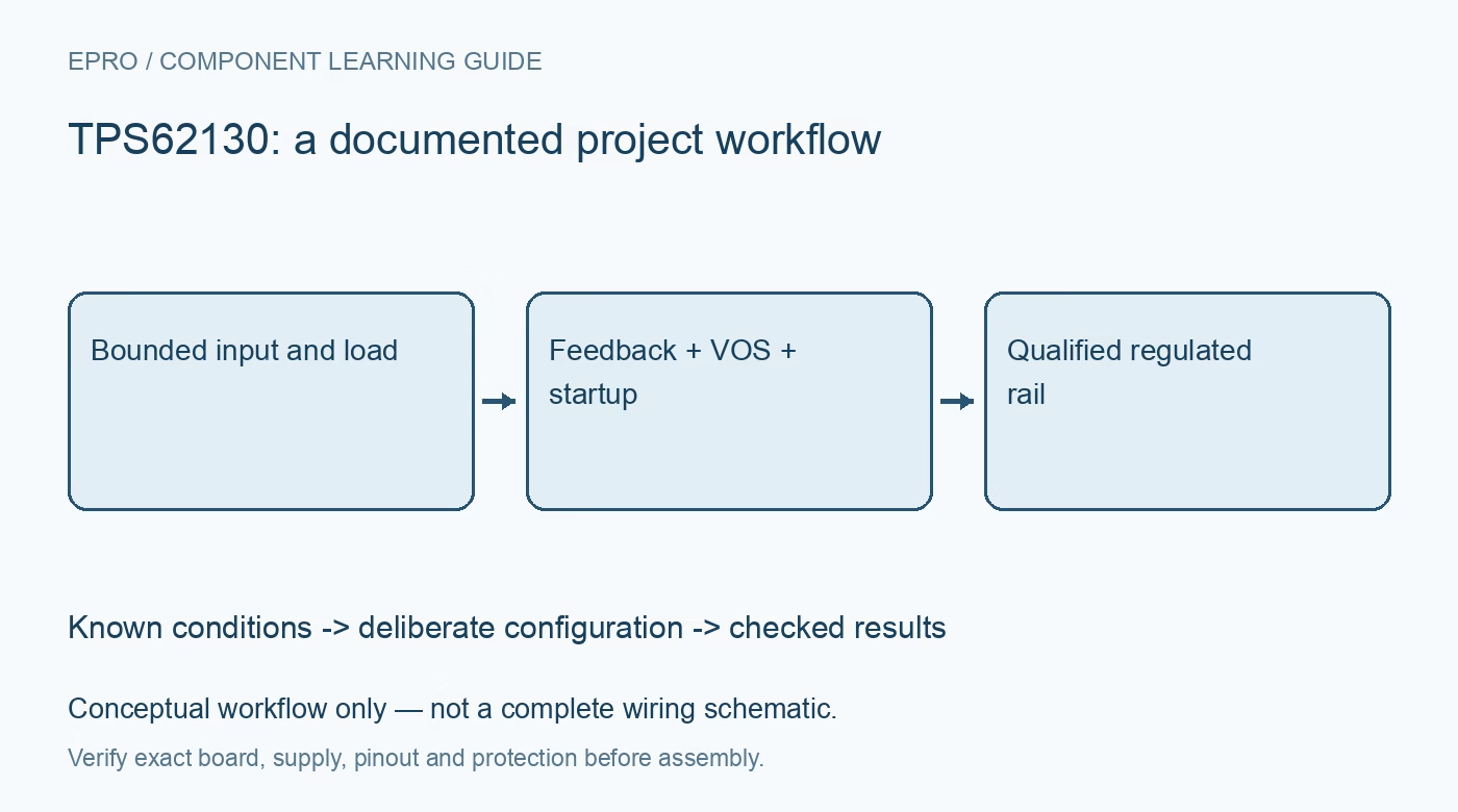
TPS62130 Buck Converter: 7 Checks for VOS, Tracking and Power Good
Check TPS62130 feedback, VOS routing, soft-start, output selection and power-good behavior before relying on a regulated low-voltage rail. This is a documentation-based planning guide, not a report of independent hands-on testing.
1. Resolve the family variant before using a schematic
TPS62130 and TPS62130A are adjustable-output members of a family that also includes fixed-voltage devices. A particularly important distinction is power-good behavior with EN low: TPS62130 is high impedance, while TPS62130A drives low. Confirm the complete part and schematic before reusing an enable-chain design. Record the intended output, input range and downstream startup requirements. Similar names do not justify copying a fixed-output connection or interpreting every family member with the same shutdown logic. Manufacturer documentation.
2. Check the buck operating envelope
The family supports a 3 V to 17 V input range and up to 3 A under applicable conditions. Those endpoints are not a guarantee of every output voltage and current combination. As a step-down converter, it cannot maintain an output above its available input. Check minimum input, conversion ratio, dropout operation, inductor current and thermal conditions for the proposed load. Use normal bounded operating tests, beginning with a current-limited source and a modest load. Manufacturer documentation.
3. Keep feedback and output sensing intentional
For the adjustable device, calculate the feedback divider using the relevant datasheet equation and recommended component guidance. VOS is the output-voltage sense connection used by the control circuitry; it is not a spare logic input or an optional indicator. Route sensing and feedback according to the layout recommendations, away from noisy switching paths. Check continuity against the assembled board and measure the regulated point. A correct divider value cannot compensate for sensing the wrong physical node. Manufacturer documentation.
4. Interpret output selection as a defined function
The device provides a pin-selectable nominal or approximately five-percent-higher output setting, not an arbitrary pair of programmable voltage presets. Establish a defined level on the relevant control pin and verify its relationship to the chosen feedback network. Include tolerances and downstream absolute limits when considering the higher setting. Test any intended transition within the recommended operating conditions. Do not treat a nominal percentage change as permission to exceed a load device’s maximum supply voltage. Manufacturer documentation.
Newest in the store


5. Plan soft-start or tracking around the load
The SS/TR connection supports controlled startup or tracking as described in the datasheet. Choose its network from the documented design procedure and account for output capacitance, startup current and downstream enable requirements. A slow programmed ramp does not remove input-current limits or guarantee that a heavy load starts successfully. Observe input voltage, output rise and load behavior together. Keep the startup record separate from steady-state efficiency or ripple measurements so each requirement has explicit evidence. Manufacturer documentation.
6. Read power good with the correct electrical meaning
PG is an open-drain indication and needs a suitable pull-up when used. Its threshold and operating conditions describe the converter output relative to its regulation target; they do not certify every downstream function. Include the TPS62130 versus TPS62130A EN-low distinction in the receiving logic. Evaluate startup and ordinary shutdown with the actual pull-up rail present. A floating PG node, an absent pull-up supply or an inverted software assumption can otherwise create a misleading ready indication. Manufacturer documentation.
7. Validate layout and representative operating points
Review the input bypass loop, inductor, switching node, output capacitors and quiet sensing routes against the manufacturer layout guidance. Record rail tolerance, startup behavior, PG response and ripple with suitable probing at representative input and load points. Include light-load operation if power-save behavior matters to the application. Do not present a single unloaded reading as full validation. Preserve component values, board revision and test conditions so a later hardware change triggers the appropriate checks again. Manufacturer documentation.
Related reading: TPS7A20 Low-Noise LDO: 7 Checks for Headroom and Real PSRR.
Catalog note: The exact-part search did not return a matching Epro listing during preparation. Check the current catalog; this guide makes no price, availability or included-accessory claim.