


PCM1808 Audio ADC: 7 Checks for Hardware Format and Clock Restart

PCM1808 Audio ADC: 7 Checks for Hardware Format and Clock Restart
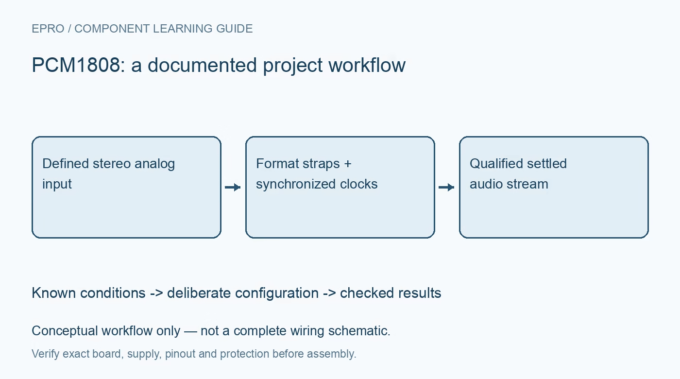
Capture PCM1808 audio with the correct dual supplies, hardware format straps, clock ratios and clock-halt recovery interval before accepting samples. This is a documentation-based planning guide, not a report of independent hands-on testing.
1. Confirm a hardware-configured stereo audio converter
PCM1808 is a stereo delta-sigma audio ADC with single-ended analog inputs and hardware-selectable audio format and clock roles. It is not the same control architecture as a software-configured audio front end with a large register map. Confirm the board schematic and the actual device before selecting a driver. Record input connectors, format straps and host capture settings together. Twenty-four-bit output words describe the interface resolution, not a promise of twenty-four-bit system accuracy or unrestricted analog bandwidth. Manufacturer documentation.
2. Provide the specified analog and digital supplies
The device uses a five-volt analog supply and a 3.3-volt digital supply under the documented operating conditions. A breakout may include additional circuitry, so verify the board rather than assuming a single connector voltage directly powers every pin. Follow bypassing and ground-return guidance. The VREF connection is a reference-decoupling node, not a general-purpose external supply output. Check all rails and control levels before attaching an external source or relying on a familiar-looking audio-module pin label. Manufacturer documentation.
3. Match the single-ended input network to audio signals
Use the manufacturer input coupling and bias arrangement for the supported signal range. Do not connect an arbitrary microphone, differential source or DC sensor directly without an appropriate interface. The converter includes audio filtering, including a high-pass function that removes the DC component. It is therefore not interchangeable with a general-purpose precision DC ADC. Start with a bounded known audio signal and conservative amplitude, then confirm both input channels independently before evaluating more complex source material. Manufacturer documentation.
4. Set format and clock roles at both ends
FMT and the mode pins select documented interface behavior, including I2S or left-justified data and the appropriate master or slave arrangement. Define their physical states and use the relevant tables instead of assuming a host’s default I2S configuration matches the board. Agree on word alignment, clock direction and slot handling. A changing serial output is not evidence that the host is collecting the correct signed samples or assigning left and right channels properly. Manufacturer documentation.
Newest in the store




5. Verify system-clock ratios and synchronization
The system clock must have a documented relationship to the sampling rate, and the audio clocks must satisfy the selected mode’s timing requirements. Inspect representative timing when necessary rather than accepting an operating-system sample-rate label as proof. Keep the actual clock source and ratio in the capture record. A valid-looking bit clock cannot substitute for a valid system-clock arrangement, and a nominally correct frequency does not establish acceptable jitter, synchronization or signal integrity at the converter pins. Manufacturer documentation.
6. Treat clock halt as reset and reacquisition
Halting SCKI invokes the documented power-down and reset behavior, with data output forced to zero. Restoring the clock does not make the first returned words immediately valid. Follow the specified reset-release, synchronization, digital-filter settling and fade-in requirements, and mark that interval as invalid audio acquisition. Clock or sample-rate changes also require the documented procedure. Do not label reset zeros as measured silence or assume a host stream that never stopped necessarily contains uninterrupted valid converter data. Manufacturer documentation.
7. Validate the complete recording and restart path
Use a known bounded tone on each input to verify amplitude, sign, channel identity and expected sampling rate. Exercise ordinary startup and the real clock-stop or restart policy, retaining raw data and invalid-interval markers. Save supply arrangement, straps, clock ratios, interface format and source conditions with the results. Headline noise and distortion figures are condition-specific. This guide describes manufacturer-based verification, not independent audio characterization; repeat the checks after changing module wiring, clock generation or the host capture format. Manufacturer documentation.
Related reading: PCM1863 Audio ADC: 7 Checks for Channel Routing and Clock Identity.
Catalog note: The exact-part search did not return a matching Epro listing during preparation. Check the current catalog; this guide makes no price, availability or included-accessory claim.