


DRV8872 Motor Driver: 7 Checks for Sleep, Braking and Current

DRV8872 Motor Driver: 7 Checks for Sleep, Braking and Current
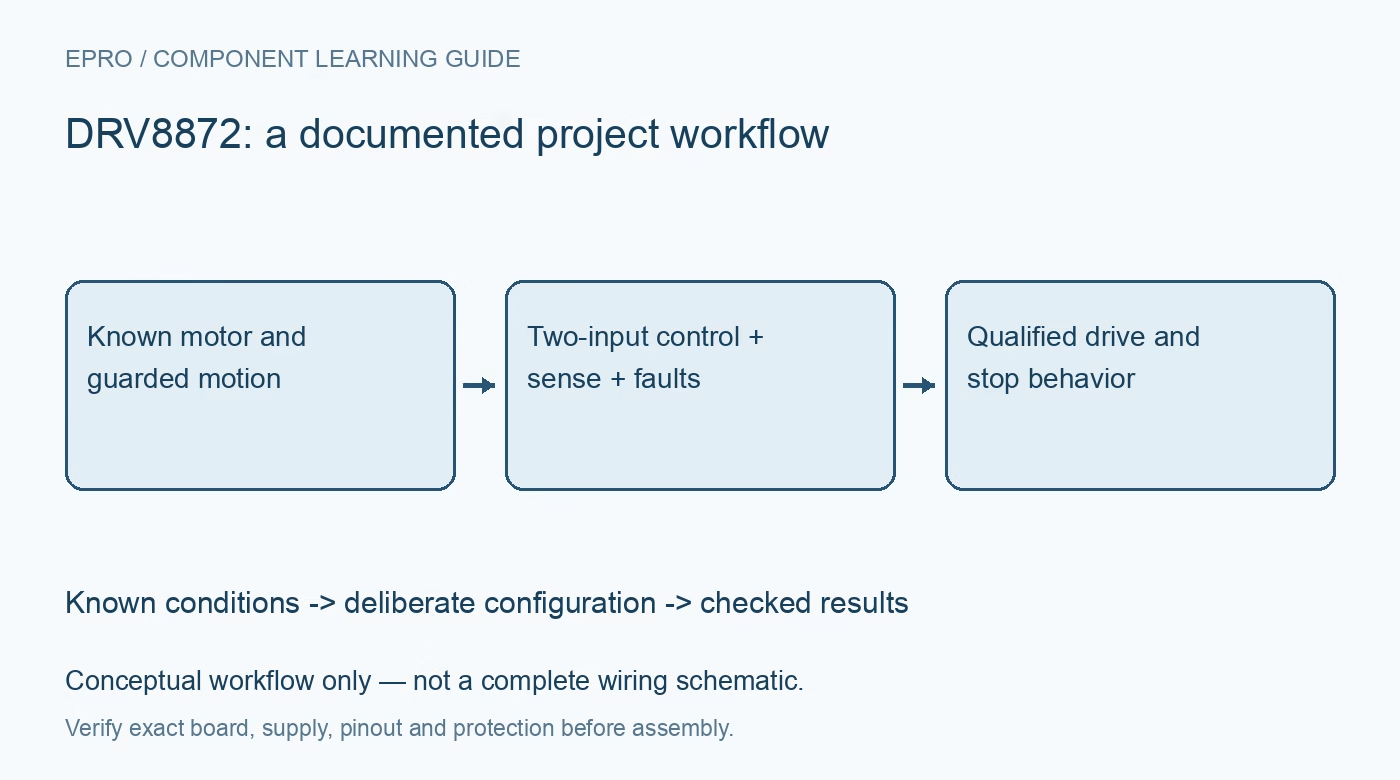
Plan DRV8872 motor control with the correct input truth table, external sense resistor, sleep timing and fault handling without assuming newer-family features. This is a documentation-based planning guide, not a report of independent hands-on testing.
1. Match motor demands to the operating envelope
DRV8872 is a brushed-DC H-bridge driver with a documented 6.5 V to 45 V operating supply range and a 3.6 A peak headline. That peak figure is not a universal continuous motor-current guarantee. Determine startup, running and stall demands along with package cooling and board copper. Guard moving parts, provide a physical way to remove motor power, and use a current-limited source for initial work. Disconnect power before changing the motor or sense-resistor wiring. Manufacturer documentation.
2. Use its two-input truth table, not another driver mode
IN1 and IN2 directly select the bridge behavior. Both low gives high-impedance outputs and coast; both high drives both outputs low for braking. The mixed states select the two current directions. This interface is not the PMODE-selected arrangement of a newer DRV8874 design. Write the truth table into the firmware specification and test with bounded motion. A software command called stop is incomplete until its electrical bridge state and mechanical consequences are defined. Manufacturer documentation.
3. Include the transition from coast into sleep
Holding both inputs low eventually enters low-power sleep, typically after about 1 ms according to the documentation. Waking then requires the specified input assertion and wakeup time before normal operation. Short PWM coast intervals and a long disabled interval therefore do not necessarily leave the device in the same internal state. Check the manufacturer timing limits rather than relying only on a typical value. An ignored-looking first pulse after a pause may be a sequencing issue, not a damaged motor. Manufacturer documentation.
4. Set current regulation with the external ISEN resistor
The current-regulation threshold is based on the voltage across the external ISEN resistance, with a typical trip voltage of 0.35 V. Use the documented tolerance range, resistor tolerance, dissipation and layout to choose a safe limit. Route the high-current return as the datasheet requires. Do not describe ISEN as the calibrated IPROPI current-mirror output found on different devices. If regulation is not used, follow the specified connection rather than leaving the current-return pin floating or improvising a firmware-only replacement. Manufacturer documentation.
Newest in the store


5. Separate current chopping from speed and torque claims
Reaching the regulation threshold initiates the documented current-decay behavior; PWM duty, motor inductance and load determine the resulting waveform. A current limit constrains electrical stress but does not directly command calibrated torque or a fixed rotational speed. Braking and coasting also produce different decay and stopping behavior. Measure current with an appropriately connected instrument during safe operation. Never insert a meter in current mode directly across the motor supply while attempting to observe the regulated current. Manufacturer documentation.
6. Treat nFAULT as a protection signal, not a stall sensor
The open-drain nFAULT output reports documented protection conditions such as undervoltage, overcurrent protection and thermal shutdown. Provide a suitable pull-up and distinguish source droop from other causes through additional observations. Ordinary current regulation is not equivalent to a uniquely decoded stall event. Automatic recovery can restart drive when the cause disappears, so firmware and machine-level controls must define the safe response. Repeated resets without investigating heating or supply collapse do not establish a reliable recovery strategy. Manufacturer documentation.
7. Test drive and stop states with a guarded sequence
Start unloaded or lightly loaded within the motor manufacturer limits, then apply only bounded, controlled load changes. Check direction, PWM behavior, braking, coast duration, wakeup and fault response without deliberately shorting outputs or forcing destructive stalls. Log motor identity, source setting, sense resistance, cooling and accepted duty cycle. Verify that power removal and firmware reset cannot cause unexpected motion. This article is a documentation-based planning aid, not evidence of measured thermal performance or functional-safety approval for a completed machine. Manufacturer documentation.
Related reading: DRV8874 Motor Driver: 7 Checks for Latched Modes and Current Feedback.
Catalog note: The exact-part search did not return a matching Epro listing during preparation. Check the current catalog; this guide makes no price, availability or included-accessory claim.