


TPS54331 Buck Converter: 7 Checks for Diode and Compensation

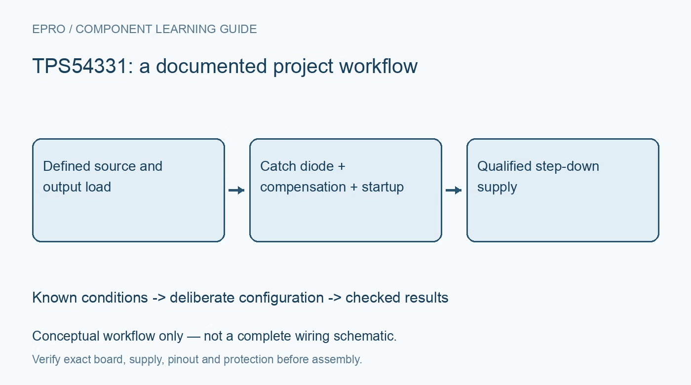
TPS54331 Buck Converter: 7 Checks for Diode and Compensation
Plan a TPS54331 buck stage with its required catch diode, bootstrap capacitor, compensation network, UVLO and realistic light-load switching expectations. This is a documentation-based planning guide, not a report of independent hands-on testing.
1. Recognize the non-synchronous power stage
TPS54331 integrates a high-side MOSFET but requires an external catch diode; it is not the same power stage as a fully synchronous buck converter. The documented input range is 3.5 V to 28 V, with up to 3 A output under suitable design and thermal conditions. Confirm the exact package and assembled circuit before applying power. A marketplace module label does not establish diode rating, cooling capability or usable continuous current at every input and output combination. Manufacturer documentation.
2. Size and place the catch diode deliberately
The diode between the switching node and ground carries inductor current during the appropriate switching interval. Select reverse-voltage, current, thermal and forward-drop characteristics using the manufacturer procedure, including switching-node excursions rather than only nominal VIN. Keep the high-current loop compact. A small diode that survives a no-load test may overheat under sustained load. Replacing it with any part described as a rectifier can alter loss and switching behavior substantially, so preserve a verified bill of materials. Manufacturer documentation.
3. Keep bootstrap and power bypassing distinct
The BOOT-to-PH capacitor provides the floating gate-drive supply and is not a capacitor from BOOT directly to ground. Follow its documented value and dielectric guidance and place it close to the relevant pins. Input bypassing has a different job: supplying switching current locally while controlling source ripple. Poor placement can cause spikes even when the bulk capacitance seems generous. Review bootstrap headroom near dropout; a high-side switch that can sometimes remain on does not turn this buck converter into a boost supply. Manufacturer documentation.
4. Recalculate compensation when changing the output filter
The external COMP network is part of the control-loop design. The manufacturer recommends a Type II compensation approach linked to the output filter and desired crossover behavior. Do not copy values from a different output voltage or substitute capacitors without evaluating the resulting loop. Include effective ceramic capacitance, ESR, inductor value and load range. A quiet steady-state voltage on a meter can coexist with inadequate phase margin or excessive ringing during a load step. Manufacturer documentation.
Newest in the store


5. Set UVLO and startup according to the real source
EN includes an internal pull-up current source, so a floating enable is not a guaranteed disabled state. The external resistor network can establish the documented undervoltage thresholds and hysteresis. Check the battery or adapter droop under startup load to prevent repeated start-stop cycles. The slow-start capacitor controls the output ramp but is not a universal hard current limiter. Account for downstream circuits that begin drawing current partway through the ramp and for the input source current-limit response. Manufacturer documentation.
6. Distinguish Eco-mode and protection from ordinary regulation
At light load the device can enter pulse-skipping Eco-mode, changing the observed switching pattern. During startup or overload, frequency foldback and current limiting can produce different waveforms again. Interpret these conditions with VIN, VOUT, load and temperature observations rather than expecting a constant switching trace at all times. The internal switch current limit is not a precision 3 A output-current controller. Repeated thermal shutdown indicates an unacceptable operating condition to investigate, not proof of a safely rated supply. Manufacturer documentation.
7. Validate the actual board across source and load extremes
Bring up with a current-limited source and noncritical load after checking polarity, diode orientation and feedback wiring with power removed. Measure output regulation, startup, ripple, load-step recovery and component temperatures at several operating points. Use a suitable short ground connection when probing switching waveforms to avoid misleading ringing or accidental shorts. Record the diode, inductor, capacitor and compensation choices. This datasheet-based guide makes no independent efficiency or continuous-current claim for an untested board. Manufacturer documentation.
Related reading: TPS62160 Buck Converter: 7 Checks for Power-Good Interpretation.
Catalog note: The exact-part search did not return a matching Epro listing during preparation. Check the current catalog; this guide makes no price, availability or included-accessory claim.