


INA181 Current Amplifier: 7 Checks for REF and Shunt Errors

INA181 Current Amplifier: 7 Checks for REF and Shunt Errors
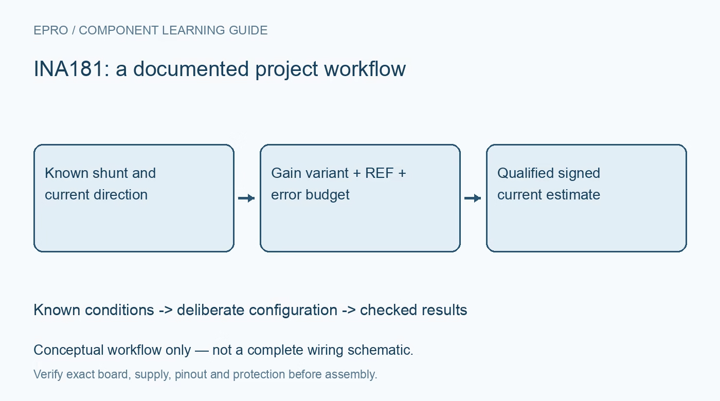
Plan an INA181 current measurement with the correct gain option, REF baseline, shunt connection and low-current error budget before converting ADC voltage. This is a documentation-based planning guide, not a report of independent hands-on testing.
1. Identify gain, package and current direction first
INA181 is the single-channel member of a bidirectional voltage-output current-sense family. The gain options are fixed by the orderable device, with A1 through A4 corresponding to different gains, not by a digital register. Confirm the exact marking and pinout before calculating current. Define positive current as the chosen voltage drop from IN+ to IN- and document the shunt orientation. A reversed sense connection changes polarity; it should not be hidden by taking an absolute value in software. Manufacturer documentation.
2. Separate bus common mode from amplifier supply
The family supports input common-mode voltages from -0.2 V to 26 V while operating from a separate 2.7 V to 5.5 V supply. This does not permit powering VS from the monitored bus at any voltage in that common-mode range. Check supply, reference and output limits independently. Include transients and ground movement at the shunt rather than considering only the nominal bus voltage. Protection and filtering must keep the real pin waveforms within the permitted operating and absolute limits. Manufacturer documentation.
3. Choose REF to leave usable headroom in both directions
The nominal transfer relation is output = REF + current times shunt resistance times gain. A midrange REF can support both current polarities, while REF at ground is commonly used for unidirectional sensing. Neither choice removes output-swing limits. Calculate both extremes with the actual ADC range and load. Supply REF from a suitable low-impedance source following the manufacturer guidance; noise or error on that baseline directly changes the inferred current and cannot be dismissed as an unrelated reference detail. Manufacturer documentation.
4. Select the shunt for loss, temperature and connection error
A larger shunt increases the signal but also increases voltage drop and heating. Calculate dissipation at the largest sustained current and include overload conditions when choosing power rating. Use sense connections that observe the intended resistor terminals rather than shared high-current copper. Shunt tolerance and temperature coefficient are part of the measurement scale. If connectors or board traces are inadvertently included in the sensed drop, a factory calibration of the resistor alone does not establish the assembled current accuracy. Manufacturer documentation.
Newest in the store


5. Quantify offset where the smallest currents matter
Input offset becomes an equivalent current error when divided by shunt resistance, so its effect can dominate near zero even when full-scale readings look reasonable. The datasheet specifies different offset conditions for low-side and higher common-mode operation; use limits appropriate to the design. Add gain error, reference error, ADC error and shunt drift rather than quoting one percentage for the whole system. A zero-current calibration should be performed only when the system can genuinely establish that no current flows. Manufacturer documentation.
6. Verify the dynamic path before reporting short pulses
Bandwidth and slew depend on the selected gain and operating conditions. The analog amplifier, any output filter and the ADC acquisition network together determine how quickly a current event is represented. Check that output capacitance and sampling kickback do not compromise settling. For switching loads, compare waveforms at the relevant time scale instead of inferring peak current from a slow average. INA181 provides an analog voltage, not timestamped digital current data, a power register or automatic coulomb counting. Manufacturer documentation.
7. Validate polarity, scale and recovery with a protected load
Use a controlled low-voltage source, a properly rated shunt and a bounded load. Compare several known currents with the calculated output, including zero and reverse current only where the complete setup supports it safely. Exercise supply startup and output saturation recovery without exceeding ratings. Save raw ADC readings alongside reference voltage and gain configuration. Manufacturer specifications guide the error budget, but the achieved current accuracy, transient performance and thermal behavior require measurements on the actual board. Manufacturer documentation.
Related reading: INA185 Current Amplifier: 7 Checks for Bidirectional REF Scaling.
Catalog note: The exact-part search did not return a matching Epro listing during preparation. Check the current catalog; this guide makes no price, availability or included-accessory claim.