


DAC8560 Voltage DAC: 7 Checks for Internal Reference Commands

DAC8560 Voltage DAC: 7 Checks for Internal Reference Commands
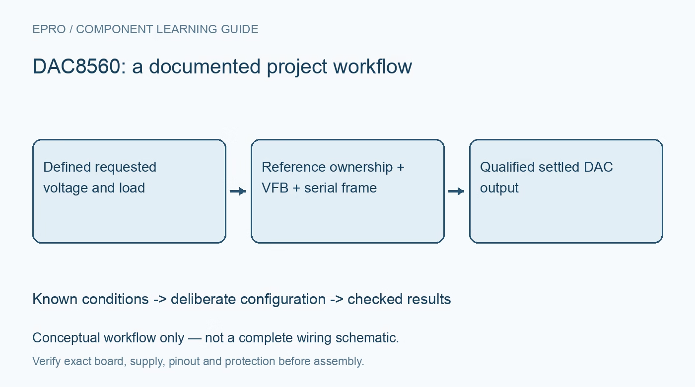
Review DAC8560 output generation with its default internal reference, external-reference handover, special clock requirements, feedback and startup behavior. This is a documentation-based planning guide, not a report of independent hands-on testing.
1. Identify the default reference before connecting a source
DAC8560 is a sixteen-bit voltage-output DAC with a 2.5 V internal reference enabled by default. This differs from a superficially similar DAC that expects only an external reference. Check the fitted part, supply range and VREF connection before applying power. The nominal internal-reference span does not automatically make the output a 0 V to supply programmable rail. Define the requested range and load separately, including output-amplifier swing, reference accuracy and the actual feedback arrangement. Manufacturer documentation.
2. Assign one active source to the VREF node
The VREF pin exposes the internal reference when it is enabled. Do not attach an external reference and assume the internal source is already disconnected. The manufacturer explicitly warns against indefinite simultaneous internal and external driving. Plan the reference handover, including startup after a power cycle, before connecting either source. Follow the required local bypassing and load guidance. An internal reference current-capability headline is conditional analog-source information, not permission to power arbitrary external circuitry without checking noise and regulation. Manufacturer documentation.
3. Treat reference-control writes as a special sequence
Ordinary data updates use a twenty-four-bit serial frame, but enabling or disabling the internal reference requires additional clock edges. The datasheet specifies at least twenty-six clocks for each reference-control update while SYNC remains low. Re-enabling uses the documented two-write sequence or a power-cycle reset. Do not invent the control words from another family member or send an ordinary three-byte write and assume the reference changed. Verify the actual sequence against the manufacturer tables and inspect VREF safely. Manufacturer documentation.
4. Complete ordinary writes without corrupting control fields
The normal input frame contains leading zeros, power-down bits and sixteen conversion-data bits, with the function applied on the documented twenty-fourth falling SCLK edge. Raising SYNC too early aborts the write without updating the DAC or mode. Keep ordinary output updates distinct from the special reference-control transaction. Validate bit order and chip-select timing with a known pattern. A stable output after a failed transfer can be the retained old code, not confirmation that the new voltage request was accepted. Manufacturer documentation.
Newest in the store


5. Close the VFB loop and calculate the actual voltage scale
VFB is part of the exposed amplifier feedback connection and must follow the chosen application circuit. For the ordinary unity-gain arrangement, use the documented straight-binary code-to-reference relation and retain the feedback connection at the intended output point. Full-scale code does not become an exact reference voltage merely because the DAC is sixteen bits wide. Include offset, linearity, reference error and load-dependent swing. A floating feedback node or an unstable remote-sense loop is an analog problem that software scaling cannot repair. Manufacturer documentation.
6. Distinguish reset, power-down and analog settling
Power-on reset sets the output to zero scale until a valid write, while serial power-down modes establish their documented output impedances. They are not all equivalent to a firmly driven zero-voltage output. Review what happens to reference ownership and the stored code across each transition, using the exact datasheet rather than an assumed family behavior. Allow the specified wakeup and settling intervals before accepting measurements. Loads that externally bias the output need separate electrical checks during disabled or unpowered states. Manufacturer documentation.
7. Validate reference ownership before testing precision
With a noncritical load, check power-up VREF and output, then verify ordinary writes at zero, midscale and near full scale. If external-reference operation is required, exercise the complete disable and restoration sequence while monitoring that only one source drives the node. Record command bytes, clock counts, supply, reference and feedback connections. Compare settled voltages with a suitable instrument and error budget. This article is documentation-based and makes no independent accuracy, glitch-energy or reference-drift claim for a finished assembly. Manufacturer documentation.
Related reading: DAC8551 Voltage DAC: 7 Checks for Feedback and Serial Updates.
Catalog note: The exact-part search did not return a matching Epro listing during preparation. Check the current catalog; this guide makes no price, availability or included-accessory claim.