


TPS22910A Load Switch: 7 Checks for Active-Low Power Control

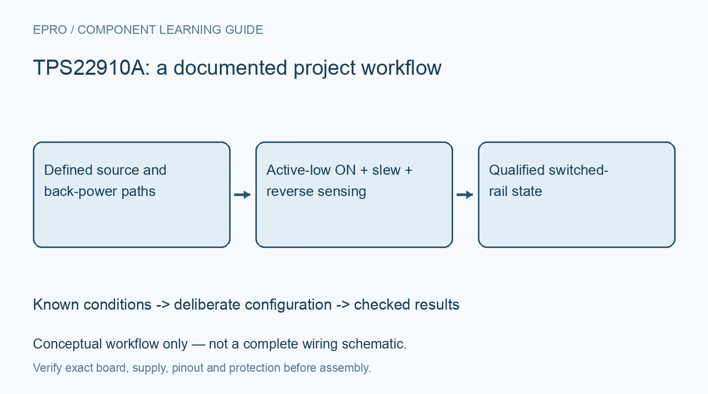
TPS22910A Load Switch: 7 Checks for Active-Low Power Control
Plan TPS22910A power switching with seven checks for active-low enable, absent output discharge, inrush, reverse-voltage protection and back-powered loads. This is a documentation-based planning guide, not a report of independent hands-on testing.
1. Read the exact device function table
The shared datasheet covers TPS22910A, TPS22912C and TPS22913B/C, but their logic and discharge behavior are not identical. TPS22910A is active low: a low ON level connects the power path, while a high level opens it. This is the opposite of the ordinary active-high assumption made in many examples. Verify the complete code, four-ball package orientation and actual board wiring before applying power. A familiar ON pin label does not define its asserted electrical level. Manufacturer documentation.
2. Keep the input and load inside their bounds
The switch operates over a 1.4 V to 5.5 V input range and has a 2 A maximum continuous switch-current headline under specified conditions. Calculate voltage drop and dissipation with the on-resistance at the real voltage and temperature. Include trace and connector loss. The part does not regulate voltage and should not be treated as a complete programmable current limiter. Review the upstream supply protection and the load fault case separately from the intended normal switching behavior. Manufacturer documentation.
3. Make boot and reset levels safe
An active-low switch can enable a load while a controller is resetting or its GPIO remains an input. Define the external bias and controller sequencing so the physical ON level matches the intended safe state throughout power-up and shutdown. Check logic thresholds at the minimum input voltage and avoid uncontrolled signal-pin current when either device is unpowered. Write the interface in terms of enable and disable operations, but preserve the inverted hardware relationship clearly in the schematic and driver. Manufacturer documentation.
4. Use the installed slew option in the inrush estimate
Controlled turn-on reduces the rate at which the load capacitor charges, but the timing differs among devices in the shared family. Use the TPS22910A switching conditions rather than a slower relative’s figures. Estimate capacitor current from capacitance times voltage slew and add any load current during startup. Then verify the source droop and output rise with representative capacitance. A small average load does not mean the initial charging pulse is harmless to a weak supply or connector. Manufacturer documentation.
Newest in the store


5. Do not borrow the relatives’ discharge resistor
Quick output discharge is provided on TPS22913B/C, not TPS22910A. When TPS22910A is disabled, the remaining output voltage depends on its capacitance, connected load and other power paths. It can therefore stay high well after the command changes. Provide a deliberate external discharge path only when the application requires it and its losses are acceptable. Opening the switch is not a guarantee of immediate zero output voltage, energy removal or galvanic isolation. Manufacturer documentation.
6. Understand voltage-triggered reverse protection
The internal reverse-voltage comparator detects VOUT above VIN by its specified threshold and turns off the pass device after a finite response time. Protection is active in both commanded states, but it is not an ideal zero-current barrier. Evaluate transient reverse current, leakage and release behavior using the stated conditions. Do not substitute the current-triggered threshold description of a different switch. Back-power through data or control lines must also be considered, because it may bypass the reviewed main power path. Manufacturer documentation.
7. Verify off, input-collapse and restart cases
Use a protected test arrangement to record normal startup, commanded disable, loss of input and an output sustained by another permitted source. Capture ON, VIN, VOUT and current direction together. Repeat at representative capacitances and loads, documenting when the output is considered safely off. Confirm that reverse protection and restart do not cause an unintended subsystem reboot loop. Treat measured results as qualified for the tested circuit rather than extending them to every possible multi-supply connection. Manufacturer documentation.
Related reading: TPS22916 Load Switch: 7 Checks for Suffixes and Reverse Blocking.
Catalog note: The exact-part search did not return a matching Epro listing during preparation. Check the current catalog; this guide makes no price, availability or included-accessory claim.