


TMP75B Temperature Sensor: 7 Checks for Rate Bits and Alerts

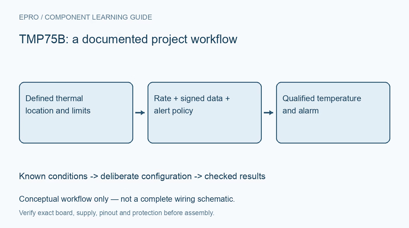
TMP75B Temperature Sensor: 7 Checks for Rate Bits and Alerts
Read TMP75B temperature with seven checks for conversion-rate bits, fixed twelve-bit data, one-shot timing, fault queues and comparator-versus-interrupt alerts. This is a documentation-based planning guide, not a report of independent hands-on testing.
1. Treat the B device as its own configuration
TMP75B is a low-voltage digital temperature sensor operating from 1.4 V to 3.6 V. Although pin and register compatibility are useful starting points, they do not make every behavior identical to another LM75 or TMP75 device. Verify the complete part code and register definitions. Strap the three address inputs deliberately to select one of eight addresses, check bus collisions and choose pull-ups compatible with the actual supply rather than a higher-voltage example board. Manufacturer documentation.
2. Recognize rate selection rather than resolution selection
The sensor produces twelve-bit temperature data with a nominal 0.0625 degree Celsius step. Its CR configuration bits select conversion rates, typically about 37, 18, 9 or 4 conversions per second. Do not reinterpret those bits as a selectable-resolution field copied from a related sensor. The trade-off is primarily update rate and current consumption, not a different output scale. Record the configured rate with the polling and alarm policy so host expectations match actual measurement freshness. Manufacturer documentation.
3. Decode signed data before applying the scale
Read the two temperature bytes in the documented order and extract the left-aligned signed twelve-bit field. Sign-extend it correctly before multiplying by the scale. Test both positive and negative examples and preserve raw bytes in diagnostics. A successful room-temperature test alone does not exercise the sign path. Distinguish resolution from accuracy: the specified temperature error is much larger than one digital step, and typical accuracy values should not be presented as guaranteed limits across the entire range. Manufacturer documentation.
4. Schedule one-shot completion without polling OS
In shutdown mode, writing one to OS initiates a conversion and the device returns to shutdown afterward. The OS bit always reads zero, so it is not a busy flag. Use the documented conversion-time limit for the applicable conditions; the electrical table gives up to 35 milliseconds for a one-shot conversion. Account for communication and host scheduling as well. Mark data invalid or stale until the requested measurement interval is complete instead of reusing a previous value as fresh. Manufacturer documentation.
Newest in the store


5. Set limits and fault queue as one policy
Program THIGH and TLOW with the correct signed format and select the intended number of consecutive fault conditions. The fault queue can require one, two, four or six qualifying conversions, so alarm latency depends on both queue depth and conversion rate. Calculate that relationship before using the sensor for thermal supervision. A threshold alone does not describe response time. Check the effective limits and polarity by readback, and keep the default register values out of an assumed production safety policy. Manufacturer documentation.
6. Distinguish comparator and interrupt clearing
Comparator mode follows the temperature thresholds with hysteresis. Interrupt mode instead latches the alert condition until a qualifying read or other documented clearing action, then changes which threshold transition can trigger the next event. In interrupt mode, even an ordinary diagnostic register read can clear ALERT. Coordinate the polling and interrupt handlers accordingly. Provide an appropriate pull-up for the open-drain output and test the selected polarity; a wire labeled ALERT does not guarantee that the host is servicing the intended state machine. Manufacturer documentation.
7. Validate freshness, alarm behavior and thermal placement
Compare readings after thermal settling with a suitably placed reference instrument. Then test threshold crossings, queue delay, interrupt clearing and shutdown-to-one-shot operation using controlled conditions within ratings. Log rate settings, raw bytes, temperature, time since acquisition and ALERT state. The sensor measures its own die and surrounding board influences, not automatically ambient air or a remote component. Preserve placement and airflow details so later mechanical changes are recognized as changes to the measurement system. Manufacturer documentation.
Related reading: TMP100 Temperature Sensor: 7 Checks for Resolution and Read Timing.
Catalog note: The exact-part search did not return a matching Epro listing during preparation. Check the current catalog; this guide makes no price, availability or included-accessory claim.