


DRV8832 Motor Driver: 7 Checks for VSET and Voltage Regulation

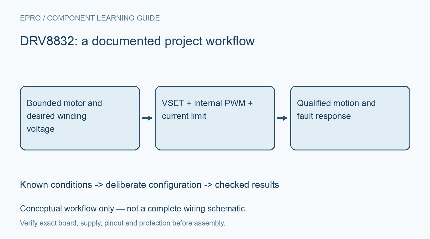
DRV8832 Motor Driver: 7 Checks for VSET and Voltage Regulation
Control a DRV8832 motor stage with seven checks for VSET voltage regulation, startup ramp, sleep logic, current-limit timing, fault recovery and load safety. This is a documentation-based planning guide, not a report of independent hands-on testing.
1. Start with a bounded motor and supply
DRV8832 provides a single H-bridge for a 2.75 V to 6.8 V motor supply, with PWM voltage regulation and current limiting. Review motor startup, stall current and mechanical load before choosing the operating point. The one-ampere class capability depends on adequate board heat dissipation and specified conditions. Secure moving parts, limit source energy and provide an accessible disconnect. A low supply voltage does not make an uncontrolled mechanism, hot winding or stalled motor harmless. Manufacturer documentation.
2. Use VSET to define the regulated voltage
The driver regulates average winding voltage by comparing a divided output observation with VSET. The nominal target is four times VSET, subject to available supply, losses and operating limits. Use the reference output and divider guidance deliberately rather than treating VSET as a generic digital PWM input. If the requested voltage exceeds what the supply can deliver, the regulation target cannot be maintained. Record the selected setpoint alongside the supply range and motor condition used for qualification. Manufacturer documentation.
3. Separate voltage regulation from closed-loop speed control
Maintaining approximately constant applied voltage can reduce speed variation caused by a changing battery, but it is not encoder-based speed regulation. Mechanical load, winding resistance, temperature and back EMF still affect actual speed. Define whether the application needs voltage control, current control or measured speed feedback before choosing acceptance criteria. A stable VSET command or apparently stable average terminal voltage cannot by itself establish constant shaft speed across arbitrary loads or a safe stall condition. Manufacturer documentation.
4. Respect the sleep, brake and ramp behavior
Inputs 00 select sleep and coast; 01 and 10 select opposite directions; 11 brakes with both outputs high. Moving from brake or sleep into drive restarts the internal voltage-control ramp, which can take up to the documented millisecond-scale interval. High-speed PWM recipes intended for a plain bridge therefore should not be copied onto these inputs. The manufacturer describes using VSET for speed adjustment; review any external-PWM exception carefully rather than repeatedly cycling the device into sleep. Manufacturer documentation.
Newest in the store


5. Calculate current limit and its time behavior
The sense threshold is nominally 200 millivolts, with specified minimum and maximum values. Choose the sense resistor from that threshold, the desired limit and its thermal requirements. Current limiting during startup is different from a persistent condition that reaches the fault deglitch interval. Review the full timing and response before allowing repeated stall operation. A calculated resistance does not establish a perfect instantaneous ceiling, and the motor, resistor and PCB must withstand the actual startup and fault-energy envelope. Manufacturer documentation.
6. Treat FAULTn and recovery as a state machine
FAULTn is an indication requiring an appropriate interface and pull-up, not a complete encoded diagnosis. Review which conditions clear automatically and which require the documented input action. Both inputs low can clear a current-limit fault, but that also changes the commanded motion state. Capture the relevant supply, current and input timing when investigating faults. Do not implement unlimited retries against a jammed mechanism or persistent short merely because a recovery sequence can restart the bridge. Manufacturer documentation.
7. Qualify startup, load changes and stopping together
Test with a secured motor and representative bounded load while recording VSET, supply voltage, winding current, input states and FAULTn. Observe the internal ramp and verify coast and brake behavior before allowing direction reversals. Check temperature after sustained operation, not just an unloaded spin. Keep measured speed separate from regulated-voltage evidence and retain the complete configuration. Release the design only for the reviewed operating envelope rather than extending a successful battery-voltage test into a general constant-speed claim. Manufacturer documentation.
Related reading: DRV8801 Motor Driver: 7 Checks for Decay Modes and VPROPI.
Catalog note: The exact-part search did not return a matching Epro listing during preparation. Check the current catalog; this guide makes no price, availability or included-accessory claim.