


TMP300 Temperature Switch: 7 Checks for Trip Resistors and Loading

TMP300 Temperature Switch: 7 Checks for Trip Resistors and Loading
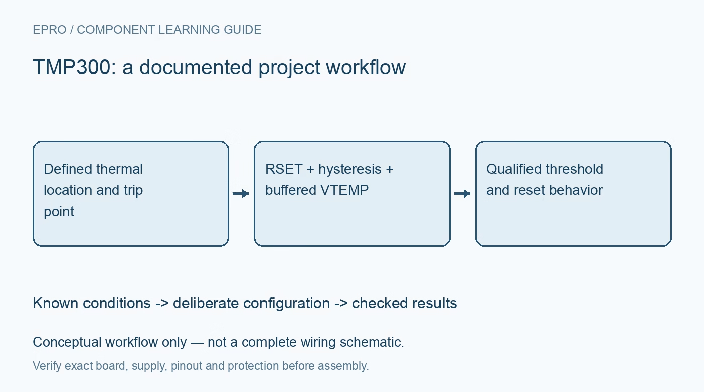
Plan TMP300 thermal switching with seven checks for resistor-set thresholds, supply-dependent range, hysteresis, analog loading and output pull-ups. This is a documentation-based planning guide, not a report of independent hands-on testing.
1. Distinguish an analog thermostat from a register-based sensor
TMP300 combines a resistor-programmable temperature trip function with an analog temperature output. It has no I2C address, conversion command or digital temperature register. The external resistor and hysteresis connection establish hardware behavior independently of firmware. Verify the six-pin SC70 or SOT-23 drawing and the exact device grade before assembly. A system can monitor its trip output with a processor, but polling software is not the mechanism that sets the basic temperature threshold. Manufacturer documentation.
2. Check supply headroom at the highest required temperature
The nominal supply range is 1.8 V to 18 V, but the full temperature measurement range is not available at every supply. Below 2.35 V, the electrical table bounds the upper measurement temperature by 100 multiplied by the quantity (supply voltage minus 0.95), in degrees Celsius. At 1.8 V that gives 85 degrees Celsius. Do not claim operation to 125 degrees Celsius just by quoting the device-wide headline. Check the table, trip accuracy and complete supply tolerance for the intended threshold. Manufacturer documentation.
3. Calculate RSET with explicit units and tolerances
The documented resistor equation is RSET in kilohms = 10 multiplied by the quantity 50 plus the desired Celsius trip temperature, divided by three. A nominal 50-degree trip therefore calls for approximately 333.3 kilohms. Select a practical value with known tolerance and temperature coefficient, then propagate its error into the threshold budget. The equation reflects the internal temperature-voltage relationship and bias current; it does not remove the device accuracy limits or make an arbitrary nearest resistor an exact calibrated set point. Manufacturer documentation.
4. Select hysteresis rather than leaving the pin undefined
Connecting HYSTSET to ground selects nominal 5-degree hysteresis; connecting it to the device supply selects nominal 10-degree hysteresis. Use the intended supply-domain connection, not an assumed midlevel third mode. Hysteresis separates trip and release conditions to reduce cycling near the threshold. Document both temperatures expected by the application, including tolerance, rather than only the rising-temperature trip. Check the complete thermal response because hysteresis cannot compensate for a sensor mounted far from the actual heat source. Manufacturer documentation.
Newest in the store


5. Buffer VTEMP before attaching a measurement system
The nominal analog output follows 10 millivolts per degree Celsius with a 500-millivolt offset, giving about 750 mV at 25 degrees Celsius. Crucially, VTEMP has approximately 210-kilohm output resistance. An ADC input, meter or filter can load that node and affect not only the measured voltage but the trip point itself. The manufacturer recommends buffering it for direct temperature measurement. Evaluate buffer input bias, leakage, offset and acquisition demand before treating an attached ADC as a harmless observer. Manufacturer documentation.
6. Treat OUT as an open-drain indication, not a power source
The output requires a suitable pull-up and a compatible receiving circuit. Size the resistor from the documented sink and leakage limits, logic thresholds and required response, and inspect the output state around the trip and release temperatures. Do not use the pin as a direct high-current fan or heater driver. A separate rated power stage and a reviewed fail-safe design are needed for such loads. Loss of sensor power, broken wiring and an unplugged pull-up should not be mistaken for confirmed safe temperature. Manufacturer documentation.
7. Validate thermal response without claiming a safety certification
Use a controlled, nonhazardous thermal setup and a suitable reference thermometer. Record mounting, supply, resistor value, hysteresis selection and whether VTEMP is buffered. Approach the threshold from both directions and allow enough time for the sensor and target to equilibrate. Repeat with the intended measurement interface attached to expose loading errors. The datasheet also describes an electrical trip-test technique, but it does not replace checking thermal coupling. Hardware threshold operation alone does not establish certification for a safety-critical protection system. Manufacturer documentation.
Related reading: TMP108 Temperature Sensor: 7 Checks for One-Shot and Alert Flags.
Catalog note: The exact-part search did not return a matching Epro listing during preparation. Check the current catalog; this guide makes no price, availability or included-accessory claim.