


TMP108 Temperature Sensor: 7 Checks for One-Shot and Alert Flags

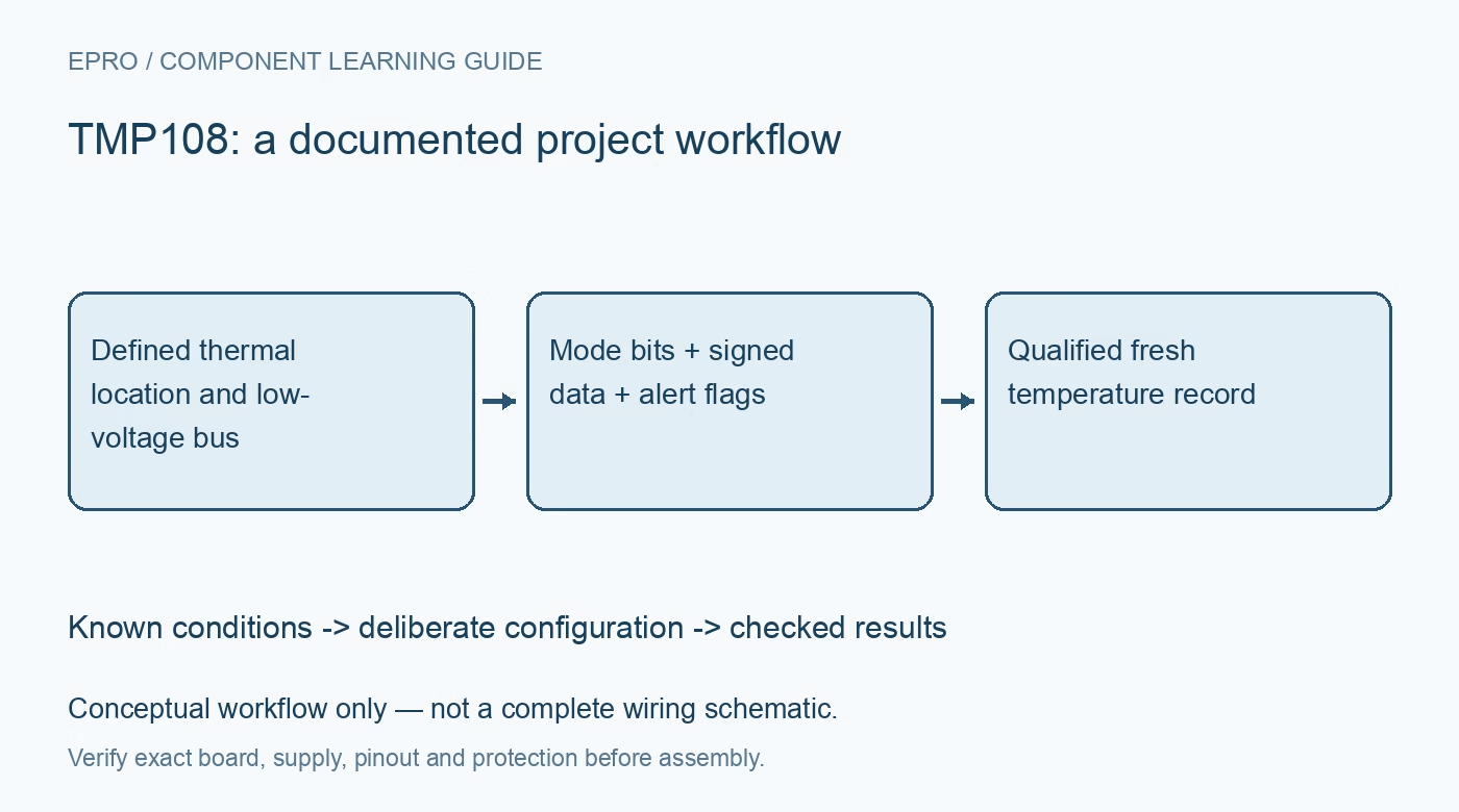
TMP108 Temperature Sensor: 7 Checks for One-Shot and Alert Flags
Plan TMP108 measurements with seven checks for address wiring, signed data, one-shot completion, conversion rates and latched temperature alerts. This is a documentation-based planning guide, not a report of independent hands-on testing.
1. Start with the low-voltage supply and address wiring
TMP108 operates from 1.4 V to 3.6 V; it is not a 5-V-powered drop-in for every temperature sensor. Its address pin supports four documented connections: ground, supply, SDA or SCL, producing seven-bit addresses 0x48 through 0x4B. The address state is latched at the beginning of communication. Follow those exact connections rather than inventing a floating-address mode, and ensure all bus pull-ups remain compatible with the sensor and host throughout power sequencing. Manufacturer documentation.
2. Decode twelve signed bits rather than an unsigned word
The temperature register is read most-significant byte first, with the top twelve bits representing two’s-complement temperature at 0.0625 degrees Celsius per count. Remove the unused low bits and sign-extend the twelve-bit field before scaling. A useful software test is 0xFF00, which represents -1 degree Celsius rather than a large positive value. Quantization step is not measurement accuracy. Test the decoder with fixed positive, zero and negative byte pairs before assessing a physical temperature source. Manufacturer documentation.
3. Distinguish power-up zero from a completed measurement
After power-up or reset, the temperature register contains zero until the first conversion completes. Therefore a readable zero is not proof that the sensor is at zero degrees Celsius. The default mode performs continuous conversions at 1 Hz, while the conversion itself is typically 27 milliseconds. Preserve timestamps and a validity state in firmware. Establish completion using the selected operating mode and documented timing, then publish the first qualified result instead of exposing an unqualified startup register value. Manufacturer documentation.
4. Use M1 and M0 to observe one-shot completion
From shutdown, writing mode bits M1:M0 as 01 starts one conversion. These bits remain 01 while the conversion runs and return to 00 when it completes. This is different from temperature sensors whose one-shot command bit always reads zero. Poll with a bounded timeout and preserve unrelated configuration fields. The electrical table gives a maximum one-shot conversion time of 33 milliseconds under specified conditions; combine that bound with transport and software scheduling margin rather than assuming every conversion takes the typical time. Manufacturer documentation.
Newest in the store


5. Separate continuous rate from conversion resolution
When M1 is one, conversion rate is selected independently by CR1:CR0, with documented choices of 0.25, 1, 4 or 16 Hz. These settings do not turn the fixed twelve-bit temperature field into a different resolution. The device converts and then waits between scheduled measurements. Repeated rapid reads can therefore return the same sample. Record rate, mode and sample age, and select an update interval that matches the thermal system rather than treating bus transaction speed as measurement throughput. Manufacturer documentation.
6. Handle upper and lower watchdog flags deliberately
TMP108 has both low- and high-limit flags, configurable hysteresis and comparator or interrupt behavior. In interrupt mode, an SMBus alert response clears the alert pin but does not clear the latched watchdog flags; reading configuration clears both the flags and the pin. A background configuration read can consequently consume evidence that another task expected to inspect. Centralize this access, record the returned flags before clearing them, and test upper-limit, lower-limit and hysteresis behavior as separate transitions. Manufacturer documentation.
7. Validate thermal placement and the complete alert path
The sensor reports the temperature of its mounted location, influenced by PCB copper, nearby heat sources and enclosure airflow. Compare against a suitable reference after thermal stabilization, and document placement and uncertainty rather than correcting an arbitrary transient offset. Test shutdown, one-shot timeout, reset and alert recovery without exposing the device to out-of-range conditions. A useful record includes raw bytes, decoded temperature, mode, timestamps and alarm state, making stale data distinguishable from a real steady temperature. Manufacturer documentation.
Related reading: TMP175 Temperature Sensor: 7 Checks for 27 Addresses and Timing.
Catalog note: The exact-part search did not return a matching Epro listing during preparation. Check the current catalog; this guide makes no price, availability or included-accessory claim.