


TMP175 Temperature Sensor: 7 Checks for 27 Addresses and Timing

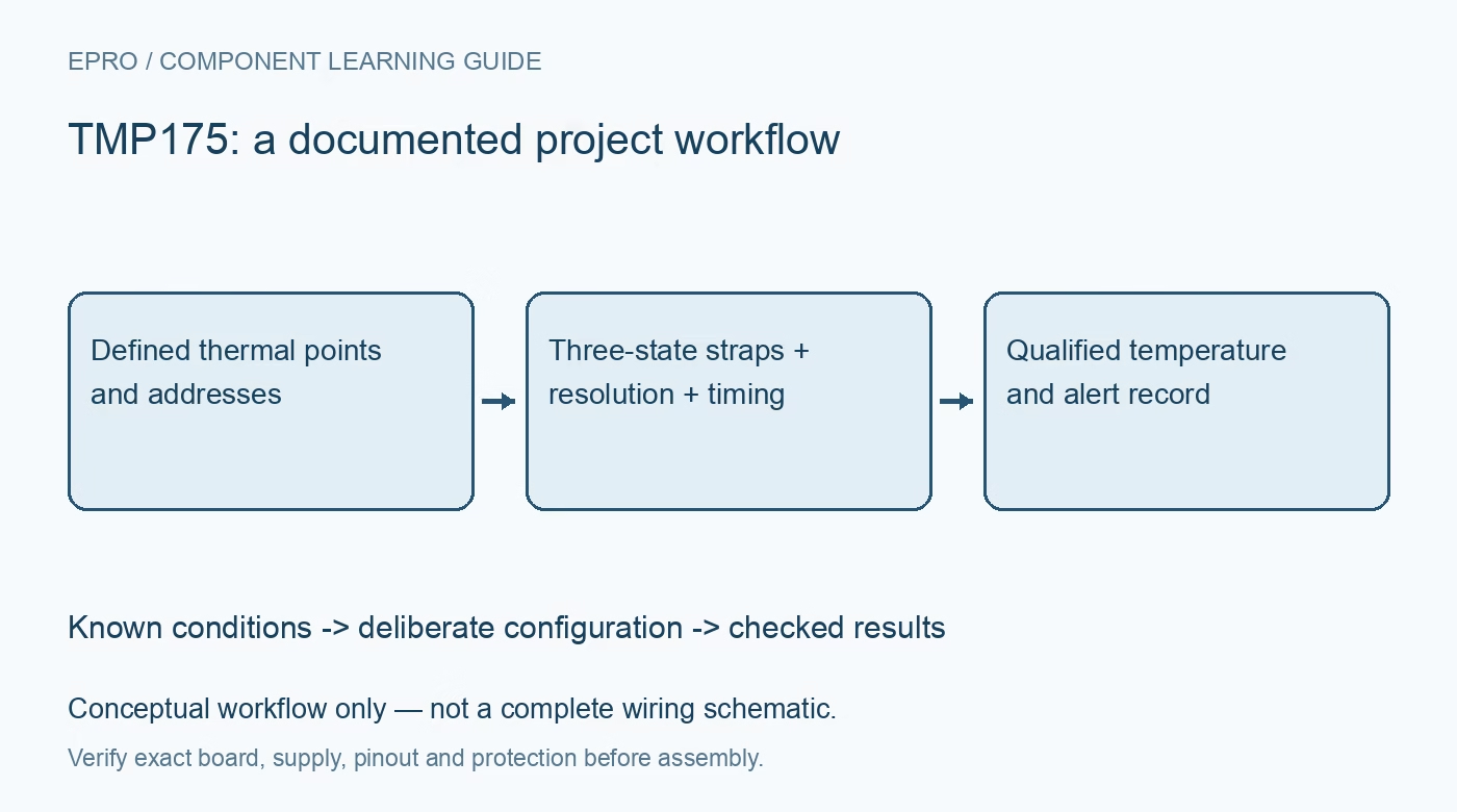
TMP175 Temperature Sensor: 7 Checks for 27 Addresses and Timing
Configure TMP175 temperature sensing with seven checks for three-state address pins, selectable resolution, conversion deadlines, one-shot reads and alerts. This is a documentation-based planning guide, not a report of independent hands-on testing.
1. Distinguish TMP175 from the related TMP75
TMP175 supports up to twenty-seven bus addresses using three-state address inputs, while TMP75 supports eight. The shared footprint and datasheet do not make their address-selection behavior identical. Confirm the installed code and package orientation before connecting the bus. Both devices use a documented 2.7 V to 5.5 V supply range, which is different from some low-voltage relatives. Check pull-up voltage and controller thresholds rather than treating every LM75-style sensor board as electrically equivalent. Manufacturer documentation.
2. Use the complete three-state address table
For TMP175, each address pin can be grounded, tied to supply or left floating according to the manufacturer map. Floating is intentional only as a documented selection, not a substitute for deciding the address. Do not invent a simple arithmetic ternary encoding for the table. Record the actual straps and seven-bit address for every sensor, then check collisions with other bus targets. Address states are sampled during communication, so keep the physical selection stable around transactions. Manufacturer documentation.
3. Choose resolution together with the acquisition interval
The configuration allows nine through twelve bits with nominal steps of 0.5, 0.25, 0.125 and 0.0625 degrees Celsius. Higher resolution takes longer to convert. The electrical table gives maximum conversion times of 37.5, 75, 150 and 300 milliseconds respectively under its specified conditions. Build polling and alarm timing around the applicable limits rather than a typical value. Store the resolution setting with the acquisition policy so later configuration changes cannot silently make readings stale. Manufacturer documentation.
4. Decode the signed temperature field correctly
Read the temperature bytes in the documented order and handle the left-aligned signed field before applying the scale. Test negative temperatures as well as positive room-temperature values, and confirm the unused low bits for the configured resolution. Keep raw bytes in diagnostics so sign-extension errors can be separated from sensor faults. Digital step size is not accuracy: the specification includes a much larger temperature-error envelope, and a smooth high-resolution trace does not establish that the measured thermal point is correct. Manufacturer documentation.
Newest in the store


5. Use a timed one-shot state machine
With the device in shutdown, writing one to OS requests a single conversion, after which it returns to shutdown. Reading OS always returns zero, so do not use it as an ordinary ready or busy flag. Wait for the applicable conversion interval and account for host and bus scheduling. Mark the reading with its age and validity. Repeatedly reading the same register faster than conversion does not produce additional independent measurements or prove the requested conversion has finished. Manufacturer documentation.
6. Design alert mode and fault queue together
Comparator and interrupt modes have different assertion and clearing rules. Configure THIGH, TLOW, polarity and the fault queue as one reviewed policy. Consecutive-fault requirements interact with conversion time, so changing resolution can also change practical alarm latency. In interrupt mode, documented read operations can clear the alert and affect the next threshold transition. Coordinate diagnostics with the interrupt handler, provide a suitable open-drain pull-up and avoid treating an address acknowledgment as proof that thermal protection is active. Manufacturer documentation.
7. Qualify the full multi-sensor installation
Validate each physical address with a known board location, then compare readings after thermal settling using an appropriately placed reference instrument. Exercise startup, one-shot acquisition and alert clearing at the selected resolution. Record straps, supply, raw bytes, configuration and acquisition timestamp. These devices sense their own die temperature, influenced by the board and airflow; they do not automatically report remote component or ambient temperature. Preserve placement and wiring details so a later board or enclosure change prompts meaningful requalification. Manufacturer documentation.
Related reading: TMP75B Temperature Sensor: 7 Checks for Rate Bits and Alerts.
Catalog note: The exact-part search did not return a matching Epro listing during preparation. Check the current catalog; this guide makes no price, availability or included-accessory claim.