


TPS7A05 Low-IQ LDO: 7 Checks for Cold Restart and Output-Discharge Options

TPS7A05 Low-IQ LDO: 7 Checks for Cold Restart and Output-Discharge Options
Check TPS7A05 suffixes, minimum-load accuracy, cold ramp-down timing and realistic battery demand before selecting a low-IQ regulated rail. This is a documentation-based planning guide, not a report of independent hands-on testing.
1. Select the fixed voltage and package deliberately
The TPS7A05 is a fixed-output LDO family with a 1.4-to-5.5-volt input range and output options from 0.8 to 3.3 volts. The output voltage is determined by the orderable part, not an external adjustment divider. Confirm the full voltage code, package and feature suffix. The three-pin package has no separate enable connection, unlike enabled variants. A pinout or feature assumption carried across packages can therefore change both shutdown control and the intended power-cycling behavior. Manufacturer documentation.
2. Budget operating current beyond the one-microamp headline
One microamp is a typical quiescent-current figure, not the total current consumed by a populated sensor rail. Add the sleeping load, leakage, pullups and any external monitoring network. The device uses adaptive and dynamic biasing, so ground current changes with load and during transients. TI lists a typical six-microamp ground current at a 200-milliamp load. Use the relevant operating conditions and limits for lifetime calculations. A low idle regulator number cannot compensate for an unexpectedly active peripheral or cross-powered interface. Manufacturer documentation.
3. Respect the minimum load for specified output accuracy
The recommended-conditions table notes that at least ten microamps of output current is required to meet the output-voltage accuracy specification. An almost unloaded rail may therefore need a separate accuracy assessment rather than inheriting every stated limit automatically. A deliberate minimum load also consumes battery current and belongs in the power budget. Distinguish typical one-percent accuracy from maximum limits and include dropout, temperature and load conditions. Check the actual rail with its intended sleep population instead of qualifying only a convenient active-load test. Manufacturer documentation.
4. Distinguish the optional discharge suffix
The optional P in the orderable designation identifies active output discharge. Devices with that option connect a nominal 120-ohm path toward ground when disabled, in undervoltage lockout or in thermal shutdown. Devices without it must not be assumed to empty an output capacitor in the same way. Evaluate the actual load in parallel with the discharge path. A separately powered peripheral can continue driving the rail, and discharge does not provide reverse-current blocking or permission to back-drive the regulator output. Manufacturer documentation.
Newest in the store


5. Review the cold ramp-down timing warning
TI gives specific power-down guidance when operating below fifteen degrees Celsius: the minimum input ramp-down time is ten milliseconds, and the minimum enable ramp-down time is one hundred microseconds. Faster transitions can produce undesired behavior at the next startup, including partial startup or a long delay. This is not captured by a room-temperature power-on demonstration. Compare the board supply and enable waveforms with that guidance, including abrupt disconnects, and decide whether the device fits the actual cold-environment restart requirement. Manufacturer documentation.
6. Check capacitance, headroom and fault behavior
Recommended output capacitance spans 0.47 to 22 microfarads; use effective capacitance after voltage bias, tolerance and temperature derating. Verify input bypassing and enough headroom at the intended current. The 200-milliamp capability does not remove the need to calculate dissipation from input-output voltage difference. Foldback current limiting reduces fault demand but can affect startup into particular loads. TI also warns against relying on active discharge after input collapse, because damaging reverse current can flow from a charged output into the input. Manufacturer documentation.
7. Qualify the actual low-power operating cycle
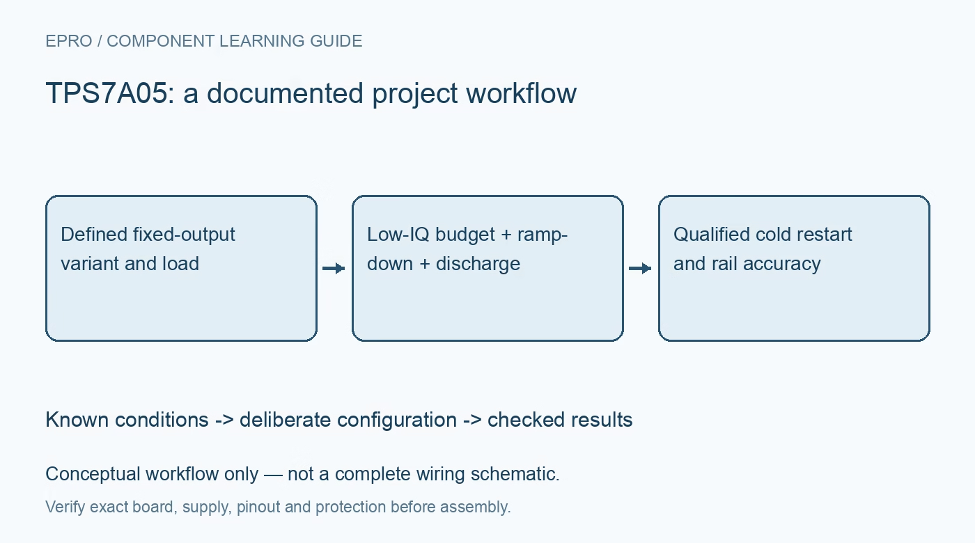
Record the complete variant, output voltage, capacitances, sleep and active loads, discharge option and temperature. With a current-limited low-voltage source, check steady-state voltage, load steps, controlled shutdown and the next restart. Include the relevant cold ramp-down conditions in the qualification plan and mark any untested conditions explicitly. Keep observations separate from calculations and manufacturer expectations. Acceptance should cover the full battery-powered duty cycle, not simply show that the regulator produces its labeled voltage once under a moderate bench load. Manufacturer documentation.
Related reading: TPS7A02 Nanopower LDO: 7 Checks Beyond Quiescent Current.
Catalog note: The exact-part search did not return a matching Epro listing during preparation. Check the current catalog; this guide makes no price, availability or included-accessory claim.