


TPS22975 Load Switch: 7 Checks for Bias Supply and CT Capacitor Ratings

TPS22975 Load Switch: 7 Checks for Bias Supply and CT Capacitor Ratings
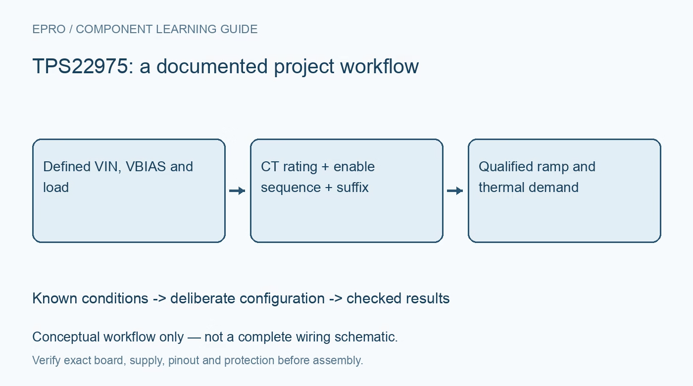
Plan TPS22975 startup with VIN-to-VBIAS limits, a correctly rated CT capacitor, suffix-specific discharge and a realistic six-amp thermal budget. This is a documentation-based planning guide, not a report of independent hands-on testing.
1. Separate the switched input from the bias supply
The TPS22975 uses VIN for the switched rail and VBIAS for its control circuitry. Recommended VIN extends from 0.6 volt up to VBIAS, while VBIAS operates from 2.5 to 5.7 volts. A low-voltage switched rail therefore does not eliminate the need for the higher bias supply. Draw both sources and their startup and removal order. Do not describe the part as an arbitrary two-supply isolator, and check the actual package pinout and exposed-pad connection before applying either rail. Manufacturer documentation.
2. Check suffix-specific behavior when disabled
TPS22975 includes quick-output discharge, whereas TPS22975N leaves the output open when disabled according to the device function table. This is a part-selection difference, not a software option shared by every populated device. The discharge path is nominally 230 ohms in the version that includes it. Identify any externally powered load connected to VOUT, because discharge can become a continuing load rather than merely removing capacitor charge. Record the complete suffix in the schematic, bill of materials and acceptance test. Manufacturer documentation.
3. Rate the CT capacitor for its own terminal stress
A capacitor from CT to ground controls slew, but the pin is not constrained to the nominal switched-rail voltage. TI states that CT can reach fifteen volts and recommends a minimum thirty-volt capacitor rating for optimal performance. Do not automatically fit a low-voltage capacitor selected for a one-volt output rail. Check dielectric, effective capacitance and placement as well as voltage rating. This requirement belongs to the timing node and remains relevant even when the visible power path operates at a much lower voltage. Manufacturer documentation.
4. Keep the timing equation within its stated conditions
TI provides an approximate CT-to-slew relationship for a five-volt bias supply, with the equation not applicable below 100 picofarads. The zero-capacitor case has separate tabulated behavior. Published rise-time values assume VIN and VBIAS have reached steady state before ON rises. A board that asserts ON while its supplies are still ramping does not reproduce those conditions. Define whether measured rise time means ten-to-ninety percent or another interval, then compare like with like when evaluating a chosen capacitor. Manufacturer documentation.
Newest in the store


5. Budget capacitor charging and operating load together
Inrush demand is approximately output capacitance times voltage slew, plus whatever current the load draws during startup. A configurable ramp reduces charging demand but is not a programmable current clamp. Include capacitor tolerance, source impedance and simultaneous downstream startup. Check input droop as well as output rise, and confirm that the load operates correctly through intermediate voltages. A slower ramp can avoid a source dip yet leave a digital device in an unintended state longer, so rail sequencing requirements must be considered separately. Manufacturer documentation.
6. Treat six amps as a conditional capability
The six-amp continuous-current headline depends on the device, package and thermal conditions. Use appropriate on-resistance limits to estimate conduction loss, then evaluate the exposed-pad layout, copper area and ambient temperature. Six amps through a nominal sixteen milliohms would already imply about 0.576 watt of conduction loss before resistance changes and other effects. Thermal shutdown is a protective response, not an acceptable normal operating thermostat. Also verify guaranteed ON thresholds; a nominal logic-voltage label is not the same as minimum controller VOH. Manufacturer documentation.
7. Validate orderly shutdown before bias disappears
TI recommends disabling the device before VBIAS falls below its recommended minimum for the best discharge results. Capture VIN, VBIAS, ON and VOUT through startup and controlled removal using bounded low-voltage conditions. Record the device suffix, CT value and rating, output capacitance, load profile and board temperature. Distinguish calculations from measured results. Do not assume that discharge, thermal protection or a low on-resistance headline establishes reverse-current blocking or a complete fault-energy limit for a cross-powered downstream subsystem. Manufacturer documentation.
Related reading: TPS22953 Load Switch: 7 Checks for Bias, Supervision and Reverse Blocking.
Catalog note: The exact-part search did not return a matching Epro listing during preparation. Check the current catalog; this guide makes no price, availability or included-accessory claim.