


TPS22953 Load Switch: 7 Checks for Bias, Supervision and Reverse Blocking

TPS22953 Load Switch: 7 Checks for Bias, Supervision and Reverse Blocking
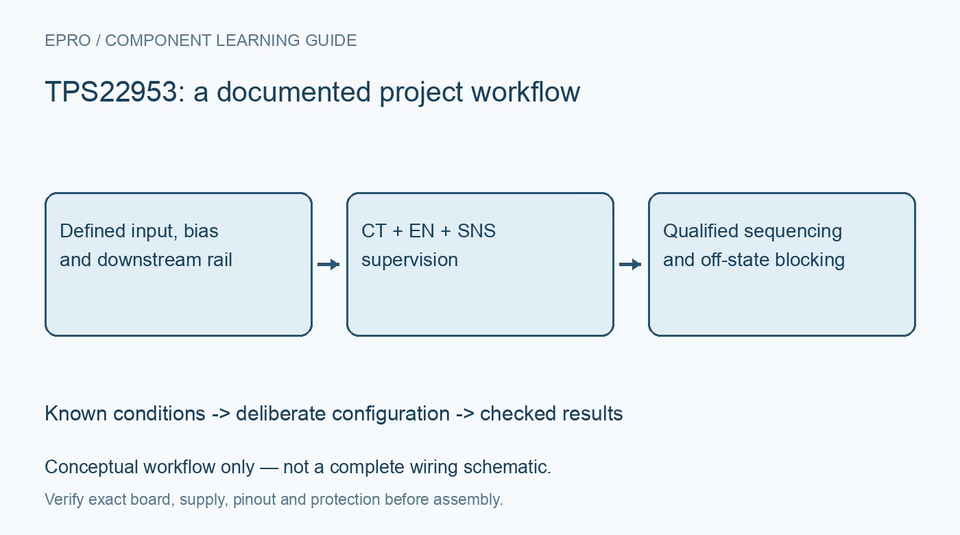
TPS22953 checks for separate BIAS requirements, slew control, SNS supervision, automatic restart and disabled reverse blocking. This is a documentation-based planning guide, not a report of independent hands-on testing.
1. Budget BIAS separately from the switched input
The TPS22953 can switch a low-voltage input, but its internal circuitry requires a separate valid BIAS supply. Recommended operation specifies VIN from 0.7 V up to VBIAS, with VBIAS from 2.5 V to 5.7 V. A 0.7 V input capability does not mean the entire device operates from a single 0.7 V rail. Draw both supplies and their sequencing explicitly. Verify every monitored and control pin against its own limits before connecting the downstream rail. Manufacturer documentation.
2. Do not confuse the 53 and 54 variants
The TPS22953 provides reverse-current blocking when disabled, whereas the TPS22954 provides the documented quick-output-discharge function. The shared datasheet overview discusses both features, so reading only a general paragraph can assign the wrong behavior to a design. Preserve the exact suffix and use the detailed feature sections. Do not promise a 15 ohm output-discharge path for the TPS22953 merely because it appears in the family description, and do not assume reverse blocking is active during normal enabled conduction. Manufacturer documentation.
3. Set inrush with CT without claiming current regulation
A capacitor from CT to ground programs the output slew rate. For non-open CT, the approximate relation is 0.35 times CT in picofarads plus 20, giving slew duration in microseconds per volt. The specified CT capacitor voltage rating is at least 25 V. Use load capacitance multiplied by voltage slew to estimate capacitive inrush, then add the active load demand. This is slew control, not a programmable constant-current limiter. Check continuous and pulse-current limits and upstream source droop separately. Manufacturer documentation.
4. Define EN and SNS as different functions
EN can implement a controlled enable or an undervoltage threshold using the recommended network. SNS monitors a selected downstream voltage through its own divider and drives supervisor behavior. The two dividers are not interchangeable copies without a threshold calculation. Include divider tolerance, leakage, hysteresis and startup sequence in the review. A chosen SNS node can be VOUT or a later rail, so document exactly what a healthy supervisor result establishes rather than calling every high power-good indication proof that the entire system is ready. Manufacturer documentation.
Newest in the store


5. Interpret power-good timing and unused-pin guidance
PG is open-drain and needs a compatible pull-up when used. It asserts only after the relevant EN and SNS conditions and the documented blanking interval; typical blanking is 100 microseconds and typical low-going deglitch is 5 microseconds. These typical values are not complete sequencing guarantees. The manufacturer directs that an unused PG pin be tied to ground. Check valid BIAS during PG interpretation and do not assume the line always provides meaningful rail status during an unpowered or partially powered condition. Manufacturer documentation.
6. Expect automatic restart after a supervisor fault
A falling SNS below its low threshold disables the switch and starts the documented restart interval, typically 2 ms. If EN remains asserted, the switch automatically attempts to enable again afterward. That behavior can repeatedly disturb a persistent faulty load; it is not a latched-off protection policy. Thermal shutdown can also recover after cooling. Test recovery using a bounded, protected load fixture and document the system’s independent fault response. Voltage supervision does not establish a precision current trip or a complete short-circuit safety mechanism. Manufacturer documentation.
7. Verify disabled reverse blocking and retained output energy
The TPS22953 reverse-current-blocking function engages after the switch is disabled, with finite response time and leakage under specified conditions. It is not instantaneous and does not actively discharge the output like the alternate QOD variant. A downstream capacitor may retain energy after disabling. Record VIN, VBIAS, EN, SNS, PG, output ramp, current and power-down behavior together. Use a separately reviewed discharge or isolation arrangement if needed, and qualify every expected backdrive scenario without exceeding the device or instrument limits. Manufacturer documentation.
Related reading: TPS22950 Load Switch: 7 Checks for Current Limits and Fault Meaning.
Catalog note: The exact-part search did not return a matching Epro listing during preparation. Check the current catalog; this guide makes no price, availability or included-accessory claim.