


TLV757P LDO: 7 Checks for a Thermally Credible 1 A Rail

TLV757P LDO: 7 Checks for a Thermally Credible 1 A Rail
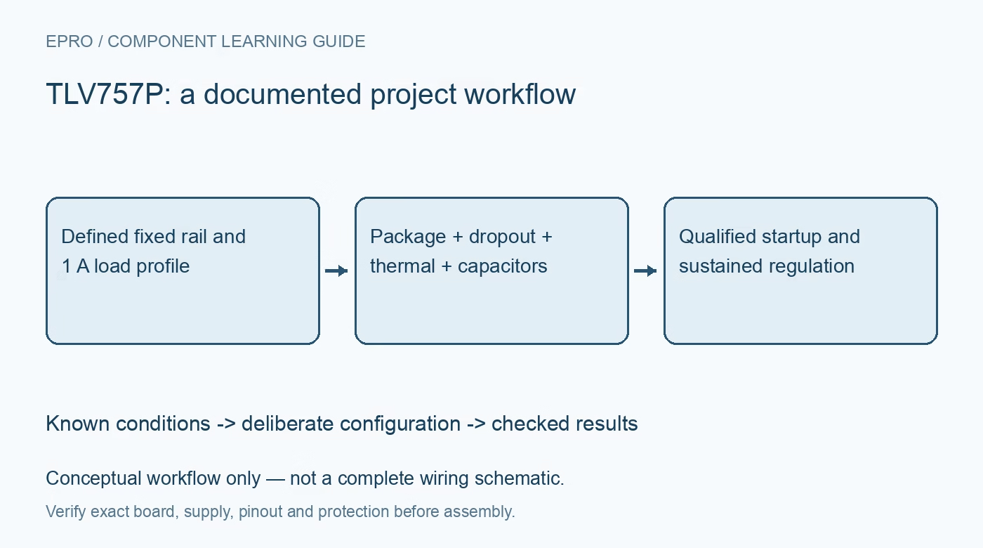
TLV757P checks for package-specific dropout, thermal copper, effective capacitors, foldback startup and reverse-current exposure. This is a documentation-based planning guide, not a report of independent hands-on testing.
1. Select the voltage suffix and package together
The TLV757P is a fixed-output LDO family operating from a 1.45 V to 5.5 V input range. Output choices and package availability depend on the complete ordering code. Its 1 A headline is conditional on electrical and thermal limits, not a guarantee that any tiny board can deliver that current continuously. Identify whether the selected package has an exposed thermal pad and follow its land-pattern requirements. A schematic symbol without package information leaves a major part of the power design unspecified. Manufacturer documentation.
2. Read the package-specific dropout rows
The 425 mV maximum dropout headline at 1 A applies to specified output-voltage and temperature conditions. The detailed table includes different limits for the thermally enhanced DYD package and for the full temperature range. Lower output voltages also have different requirements. Use the row matching output, package, current and junction-temperature envelope rather than copying the front-page number universally. Include source sag and connector loss when determining the minimum input required to keep the final rail regulated. Manufacturer documentation.
3. Convert input headroom into a heat budget
The main dissipation estimate is input minus output voltage multiplied by load current. At 5 V in and 3.3 V out, 1 A implies approximately 1.7 W before smaller contributions are considered. That arithmetic does not establish that the selected package and board can dissipate it. Estimate junction temperature using an appropriate layout and thermal model, accounting for ambient and neighboring heat sources. Extra input headroom can improve dropout margin while simultaneously making the thermal problem substantially worse. Manufacturer documentation.
4. Verify effective capacitance at both pins
Use the documented nominal input and output capacitors, with at least 1 microfarad specified in the pin guidance, and ensure effective capacitance remains greater than 0.47 microfarad after derating. Ceramic DC bias, tolerance and temperature matter. The application recommends keeping output capacitance within its stated range, including the 200 microfarad guidance for best performance. Place capacitors close to the required current paths. A nominal capacitor value or a successful no-load startup does not independently demonstrate stability over the intended operating envelope. Manufacturer documentation.
Newest in the store


5. Check foldback against the actual startup load
Below approximately 0.4 times nominal output voltage, the regulator changes to foldback current limiting. A constant-current downstream load can demand more than the available startup current and prevent the output from reaching its intended rail. Sequence such a load after the output rises when the application requires it. Internal soft-start does not cancel that interaction. Compare the real load profile, capacitor charging demand and limit behavior; a rail that starts with a resistor may fail with the actual powered subsystem. Manufacturer documentation.
6. Review enable and output-backdrive scenarios
EN control needs a deliberate startup state. Driving EN above VIN can increase current, and the manufacturer gives additional restrictions when that condition occurs. Active output discharge during shutdown is not reverse-current blocking. An externally driven output or collapsing input can send current through the pass-transistor body diode; VOUT above VIN plus 0.3 V exceeds the stated limit. Use appropriate external protection if the system can create that condition, and do not assume an LDO safely isolates two independently powered rails. Manufacturer documentation.
7. Qualify sustained delivery without thermal cycling
Record the full ordering code, copper implementation, ambient conditions, input range, effective capacitance, load transitions, ramp and temperature. Test the lowest-headroom condition and the highest-dissipation condition separately because they are not necessarily the same operating point. Thermal shutdown can automatically restart, but repeated cycling indicates an unacceptable normal design and can reduce reliability. The acceptance result should establish a regulated rail with thermal margin, not simply demonstrate that the board eventually produces the nominal voltage between shutdown events. Manufacturer documentation.
Related reading: TLV755P LDO: 7 Checks for Startup, Dropout and Reverse Current.
Catalog note: The exact-part search did not return a matching Epro listing during preparation. Check the current catalog; this guide makes no price, availability or included-accessory claim.