


TCA9511A Hot-Swap I2C Buffer: 7 Checks Before Treating READY as Device Health

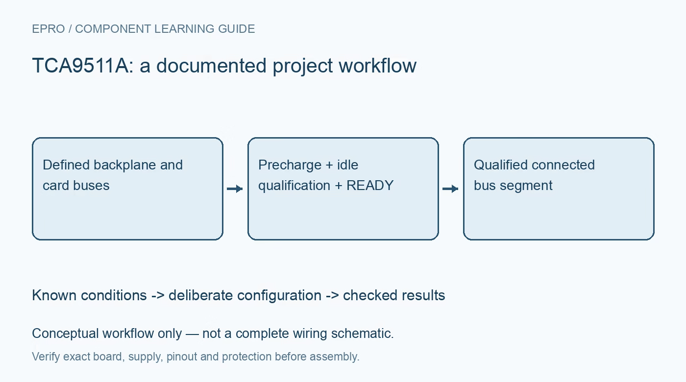
TCA9511A Hot-Swap I2C Buffer: 7 Checks Before Treating READY as Device Health
Check TCA9511A precharge, bus-idle connection, READY pullups and low-level offsets before qualifying a hot-swappable I2C segment. This is a documentation-based planning guide, not a report of independent hands-on testing.
1. Define the card boundary and connection direction
The TCA9511A supports hot insertion by keeping its IN-side backplane and OUT-side card bus disconnected until the documented conditions permit connection. It operates from a 2.3-to-5.5-volt supply. Mark the actual backplane and removable-card sides in the schematic and connector documentation, then identify their pullups, capacitances and power states. The buffer is not a complete hot-plug power controller: connector sequencing, ground continuity, electrostatic protection and card power inrush still need separate assessment before live insertion is attempted. Manufacturer documentation.
2. Understand the limited role of precharge
After the supply exceeds undervoltage lockout, enabled precharge biases the bus pins to approximately one volt through nominal 100-kilohm paths. This reduces the voltage disturbance associated with attaching the local parasitic capacitance. It is not a strong pullup that establishes a normal I2C high level, and it does not force an external device to release a held-low line. Check precharge in the context of the actual powered backplane. Do not interpret a one-volt disconnected-line measurement as proof that communication is ready. Manufacturer documentation.
3. Verify both connection qualifiers and card-side release
The buffer waits for a STOP condition or the required idle interval on the IN side. The OUT-side SDA and SCL lines must also be high before the segments are joined. A card device holding its bus low can therefore prevent connection even when the backplane appears idle. Design controller software to wait for the documented connection indication and to handle timeout explicitly. Repeatedly toggling enable without diagnosing the card state is not evidence that the hot-swap function has failed. Manufacturer documentation.
4. Read READY as connection status, not target health
READY is an open-drain signal that remains low while the sides are disconnected and releases high when connection has been established. It requires a compatible external pullup. A high indication does not prove that every target acknowledges, that the intended firmware has booted or that all bus timing margins are adequate. Check the signal against a known transaction separately. An absent pullup, broken connection or mismatched controller threshold can otherwise make a valid buffer state appear misleading in software. Manufacturer documentation.
Newest in the store


5. Account for pullups, accelerators and low-level offsets
Rise-time accelerators assist positive bus transitions, but external pullup selection and segment loading still matter. A forwarded low also includes an offset used for direction recognition. In cascaded arrangements, low-level offsets can accumulate and reduce the receiving device margin. Use the maximum relevant limits and supported topology examples rather than multiplying a typical number and calling the result guaranteed. Observe both sides during reads, writes, stretching and arbitration-related transitions; a static meter reading cannot establish dynamic compatibility. Manufacturer documentation.
6. Distinguish isolation from stuck-bus recovery
EN low disables the accelerators and precharge circuitry, isolates the bus segments and pulls READY low. Supply below undervoltage lockout gives the specified high-impedance behavior. Once connected, however, the buffer does not automatically become a full stuck-bus recovery controller simply because it has a READY output. Define what the host does if a target later holds a line low. Disabling a segment may contain the fault, but recovering the target and restoring valid transactions require an explicit system-level sequence. Manufacturer documentation.
7. Qualify insertion only after bounded bench checks
Begin with fixed low-voltage wiring and a current-limited source, checking enable, idle qualification and READY before evaluating an appropriately designed removable interface. Record rail values, pullups, capacitance estimates, connector arrangement and controller timing. Capture the backplane and card lines through connection and deliberate disable, then verify clock stretching and representative transactions. Mark measured observations separately from datasheet expectations. Passing one address scan after insertion is not proof that the card can be safely inserted under every bus, power and environmental condition. Manufacturer documentation.
Related reading: TCA9517 I2C Repeater: 7 Checks for Buffered Lows and Bus Topology.
Catalog note: The exact-part search did not return a matching Epro listing during preparation. Check the current catalog; this guide makes no price, availability or included-accessory claim.