


LP5024 RGB LED Driver: 7 Checks for Bank Control and Dithered Dimming

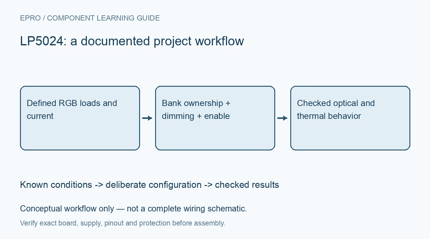
LP5024 RGB LED Driver: 7 Checks for Bank Control and Dithered Dimming
Plan an LP5024 RGB design with verified bank ownership, current settings, PWM dithering, startup states and thermal limits. This is a documentation-based planning guide, not a report of independent hands-on testing.
1. Identify the 24-channel sink architecture
Start with the board schematic rather than a generic RGB diagram. LP5024 provides 24 constant-current sink outputs, enough for eight three-channel RGB groups; these outputs are not voltage sources. Identify LED polarity, the separate LED supply where used, the logic supply and the current-setting components. The documented VCC range is 2.7V to 5.5V. Check output-pin limits separately instead of assuming an LED rail can follow any available system voltage. Manufacturer documentation.
2. Choose current before choosing brightness
The current ceiling is supply-dependent: the family documentation lists 25.5mA per channel across the full supply range and 35mA when VCC is at least 3.3V. These are not instructions to operate every LED at maximum current. Check the current-setting resistor, configuration and LED ratings together. Begin at a conservative setting, then measure actual channel current. PWM brightness changes average light output but does not remove the need to respect the programmed on-current. Manufacturer documentation.
3. Separate color from group brightness
Individual color-mixing values and RGB-group brightness controls have different jobs. Keep the channel map next to the register configuration so red, green and blue cannot silently exchange positions. Establish a known test pattern with only one color active, followed by a brightness sweep at a fixed color ratio. Record whether linear or logarithmic mapping is selected. A visually smooth fade is not proof of a linear electrical transfer or a calibrated optical output. Manufacturer documentation.
4. Make bank ownership explicit
Bank mode overrides the independent color and brightness controls for the selected RGB group. A write to an individual channel can therefore succeed on the bus while leaving the visible output unchanged. Maintain a software ownership table showing which groups use individual control and which use the shared bank registers. Test ownership changes with low-current patterns first. Restore both the bank-enable configuration and the relevant color values after reset rather than relying on an earlier animation state. Manufacturer documentation.
Newest in the store


5. Understand what 12-bit dimming means
The internal PWM engine operates around 29kHz, but the documented 12-bit duty-cycle accuracy combines nine bits of PWM with three bits of digital dithering. Disabling dithering leaves nine-bit duty-cycle accuracy. Consequently, one captured pulse does not necessarily represent the long-term average brightness command. For waveform review, capture enough consecutive periods to see the dither sequence, and record the dithering setting alongside the register values. Do not describe the interface as a direct 12-bit-per-channel brightness register. Manufacturer documentation.
6. Qualify enable, shutdown and recovery
Use a defined EN state and follow the documented chip-enable sequence before enabling light output. Check address straps, pullups and logic levels against the actual controller and board. Prepare a dark startup state so a controller reset does not briefly display a stale or unintended pattern. Exercise power removal and restoration with the LED rail present and absent as permitted by the datasheet. Confirm that firmware restores configuration before restarting an animation, rather than trusting a successful address acknowledgement. Manufacturer documentation.
7. Check the complete all-channel load
Estimate dissipation from sink current, duty cycle and the voltage remaining across each output. Phase shifting can reduce simultaneous supply-current steps, but it does not eliminate average power or package heating. Use a current-limited supply, then observe supply droop, current, temperature and visible artifacts during a bounded all-channel pattern. Preserve the LED type, board revision, current setting and measurement conditions with the results. Treat this as a qualification plan, not evidence that a particular module has already passed it. Manufacturer documentation.
Related reading: LP5036 RGB Driver: 7 Checks for Color, Brightness and Dithered PWM.
Catalog note: The exact-part search did not return a matching Epro listing during preparation. Check the current catalog; this guide makes no price, availability or included-accessory claim.